
1. Introduction
This manual provides comprehensive instructions for the assembly and operation of the MiOYOOW LED Traffic Light Simulation Soldering Practice Kit. This kit is designed to offer a hands-on learning experience in basic electronics, soldering techniques, and the principles of traffic light sequencing. It is suitable for educational purposes and hobbyists interested in STEM projects.
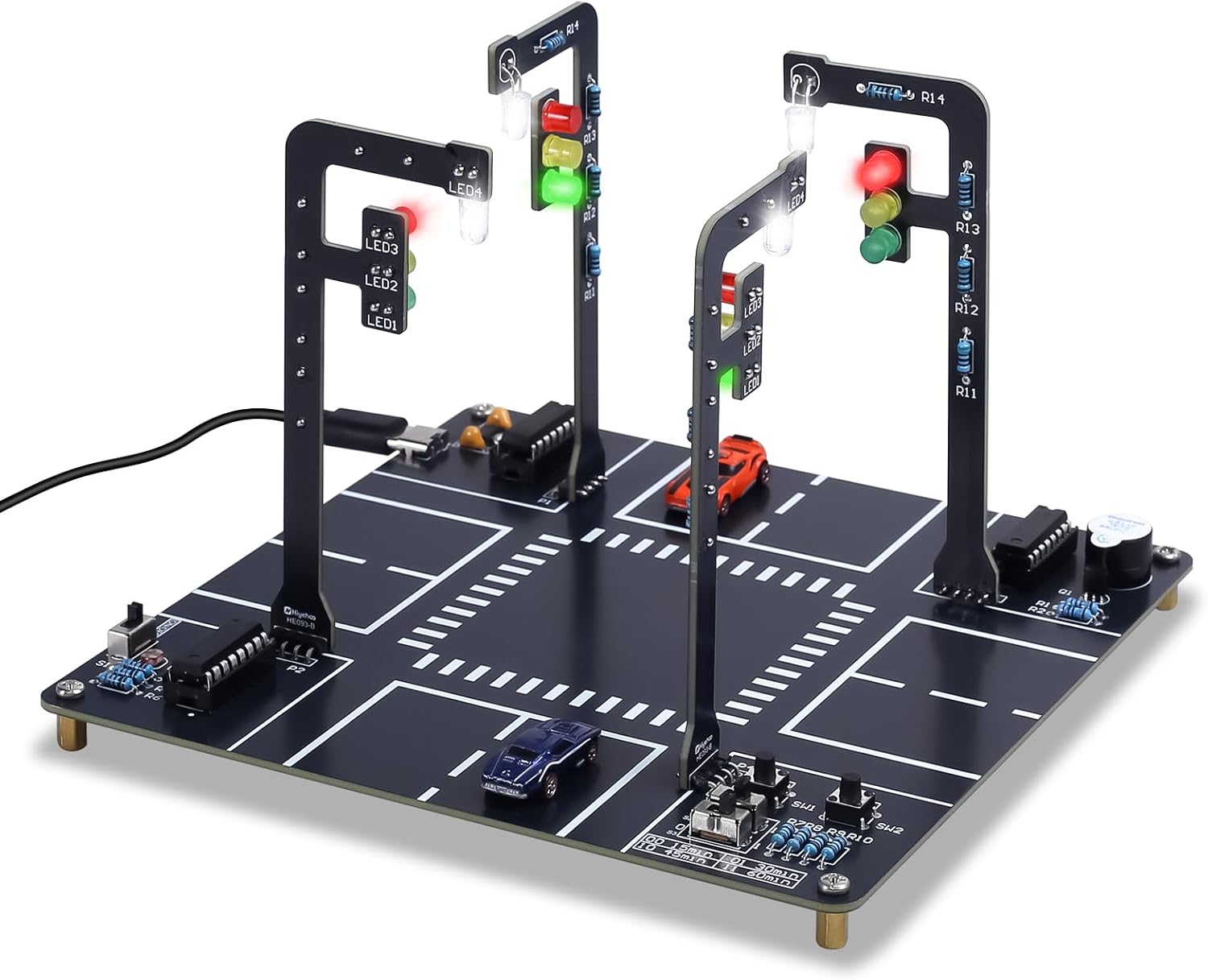
Image 1.1: Fully assembled MiOYOOW LED Traffic Light Simulation Soldering Practice Kit, showcasing the traffic lights, PCB layout, and mini cars.
2. Safety Information
Please read and understand the following safety guidelines before beginning assembly or operation:
- Eye Protection: Always wear appropriate eye protection (e.g., safety glasses) when soldering or cutting component leads to prevent injury from flying debris or solder splashes.
- Ventilation: Ensure adequate ventilation in your workspace to avoid inhaling solder fumes.
- Hot Surfaces: Soldering irons become very hot. Handle with care and place them in a safe holder when not in use. Allow components and solder joints to cool before touching.
- Electrical Safety: This kit operates at low voltage. However, always ensure the power supply is disconnected before making any changes to the circuit.
- Adult Supervision: For younger users, adult supervision is recommended during the soldering process.
- Component Handling: Some electronic components can be sensitive to electrostatic discharge (ESD). Handle them by their edges or leads, and consider using ESD-safe practices if available.
3. Package Contents
Verify that all components listed below are present in your kit before starting assembly. If any parts are missing or damaged, please contact customer support.

Image 3.1: Overview of all components included in the kit, laid out for identification.
- Printed Circuit Board (PCB) with traffic intersection layout
- LEDs (Red, Yellow, Green, White)
- Resistors of various values
- Integrated Circuits (ICs) and IC sockets
- Capacitors
- DIP switches
- Push buttons
- Light sensor (Photoresistor)
- Buzzer
- USB power cable
- Miniature car models (x2)
- Mounting hardware (screws, standoffs)
- Traffic light PCB structures (x4)
- Other small electronic components as required for the circuit
4. Assembly Instructions
This kit features a clearly labeled circuit board, simplifying the soldering process. It is recommended to have a basic understanding of electronics and soldering techniques for the best experience. Follow the steps carefully.

Image 4.1: An adult and child engaged in soldering, demonstrating the hands-on nature of the kit.
4.1. Component Identification and Preparation
- Identify all components using the provided component list and the markings on the PCB.
- Pay attention to polarity for components like LEDs, diodes, and electrolytic capacitors. The PCB usually indicates the correct orientation.
- Bend the leads of through-hole components to fit into their designated holes on the PCB.
4.2. Soldering Process
Solder components onto the PCB in a systematic manner, typically starting with the lowest profile components first (e.g., resistors, diodes) and progressing to taller components (e.g., IC sockets, capacitors, buttons).
- Insert the component into its designated holes on the PCB.
- Flip the PCB over and gently bend the leads outwards to hold the component in place.
- Heat both the component lead and the PCB pad simultaneously with the soldering iron.
- Apply a small amount of solder to the heated joint, allowing it to flow smoothly around the lead and pad.
- Remove the solder, then remove the soldering iron. The joint should be shiny and cone-shaped.
- Trim excess leads using flush cutters after the solder has cooled.
- Install ICs into their sockets only after all soldering is complete and the board has cooled. Ensure correct orientation (notch on IC matches notch on socket/PCB).
4.3. Assembling Traffic Light Structures
- Solder the red, yellow, and green LEDs onto the smaller traffic light PCB structures. Observe polarity.
- Attach these assembled traffic light structures to the main PCB using the provided standoffs and screws.
- Solder the white LEDs for the streetlights onto their designated positions.
5. Operating Instructions
Once assembled, the traffic light simulation kit offers various modes and interactive features.

Image 5.1: The traffic light simulation demonstrating the sequence of red, yellow, and green lights, accompanied by a buzzer sound.
5.1. Powering the Device
Connect the provided USB cable to the kit's power input and to a standard USB power source (e.g., computer USB port, USB wall adapter).
5.2. Modes and Timing Functions
The kit supports both automatic and manual light switching, with adjustable timing intervals.

Image 5.2: Illustration of DIP switch configurations for setting traffic light intervals (15s, 30s, 45s, 60s).
- Automatic Mode: In this mode, the LEDs cycle through preset traffic sequences automatically.
- Manual Mode: Users can control the lights using the designated button.
- Timing Options: Four timing options (15s, 30s, 45s, and 60s) can be selected via the DIP switches on the PCB. Adjust these switches to set the desired interval for the traffic light sequence.
- Buzzer: A built-in buzzer emits a sound when the traffic lights transition between red and green.
5.3. Light-Controlled Streetlamp
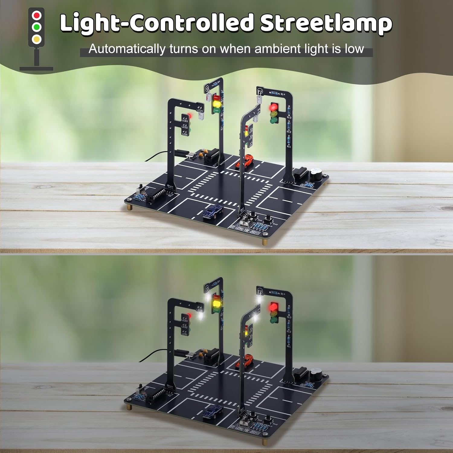
Image 5.3: The light-controlled streetlamp feature, demonstrating how the white LED activates automatically in low ambient light.
The kit includes a built-in light sensor. This sensor automatically activates a white LED, mimicking a streetlight turning on when ambient light levels are low.
5.4. Interactive Features

Image 5.4: The two mini cars provided with the kit, used for simulating vehicle movement on the intersection.
The PCB features printed lanes and crosswalks for a realistic intersection setup. Two mini cars are included to simulate vehicle movement and stopping behavior in response to the signal changes, enhancing the interactive experience.
6. Specifications
| Feature | Detail |
|---|---|
| Product Dimensions | 3.93 x 3.93 x 0.7 inches |
| Item Weight | 6.4 ounces |
| Manufacturer Recommended Age | 3 years and up (with supervision for soldering) |
| Power Source | USB (cable included) |
| LED Colors | Red, Yellow, Green (Traffic Lights), White (Streetlamp) |
| Operating Modes | Automatic, Manual |
| Timing Intervals | 15s, 30s, 45s, 60s (selectable via DIP switches) |
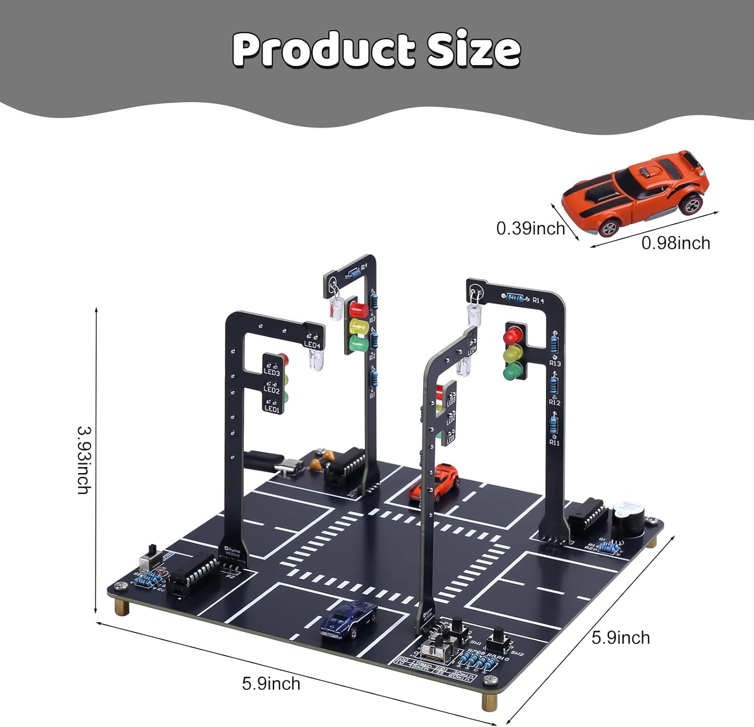
Image 6.1: Visual representation of the product's dimensions.
7. Troubleshooting
If you encounter issues with your MiOYOOW LED Traffic Light Simulation Soldering Practice Kit, consider the following common troubleshooting steps:
- No Power: Ensure the USB cable is securely connected to both the kit and a working power source. Try a different USB port or adapter.
- LEDs Not Lighting Up:
- Check for correct LED polarity during soldering. LEDs are diodes and only work when current flows in one direction.
- Inspect solder joints for cold joints (dull, lumpy appearance) or bridges (solder connecting two adjacent pads). Re-solder as necessary.
- Verify that the correct resistor values are used for each LED.
- Incorrect Traffic Light Sequence/Timing:
- Ensure DIP switches are set correctly for the desired timing interval.
- Check connections to the ICs and ensure they are correctly seated in their sockets.
- Buzzer Not Sounding: Check the buzzer's polarity and solder connections.
- Streetlamp Not Activating: Ensure the light sensor (photoresistor) is correctly installed and its connections are sound. Test in varying light conditions.
- Intermittent Operation: Re-examine all solder joints for any loose connections or cracks.
If problems persist after these checks, please refer to the contact information in the Support section.
8. Maintenance
The MiOYOOW LED Traffic Light Simulation Soldering Practice Kit requires minimal maintenance to ensure its longevity and proper function.
- Cleaning: Keep the PCB and components free from dust and debris. Use a soft, dry cloth or a small brush to gently clean the surface. Avoid using liquids directly on the circuit board.
- Storage: Store the kit in a dry, cool environment away from direct sunlight and extreme temperatures.
- Handling: Handle the assembled kit with care to avoid bending or breaking components, especially the traffic light structures.
9. Warranty and Support
MiOYOOW products are designed for quality and educational value. For any questions, technical assistance, or warranty inquiries regarding your LED Traffic Light Simulation Soldering Practice Kit, please contact MiOYOOW customer support through the retailer where the product was purchased.
Please provide your purchase details and a clear description of the issue to facilitate a quicker resolution.