1. Introduction
This instruction manual provides comprehensive guidance for the assembly, setup, and operation of your MiOYOOW HC-SR04 Ultrasonic Ranging Alarm and LED Desk Lamp DIY Kit. This kit is designed to enhance soldering skills and provide an educational experience in electronics. Please read this manual thoroughly before beginning assembly.

Figure 1.1: The MiOYOOW HC-SR04 Ultrasonic Ranging Alarm and LED Desk Lamp DIY Kit. This image displays both the ultrasonic ranging alarm module and the LED desk lamp, showcasing the two distinct projects included in the kit.
2. Safety Information
Always observe the following safety precautions when working with electronic components and soldering equipment:
- Ensure adequate ventilation when soldering to avoid inhaling fumes.
- Wear appropriate eye protection to shield against solder splashes or flying debris.
- Use a heat-resistant mat to protect your work surface.
- Handle hot soldering irons with extreme care to prevent burns.
- Keep all electronic components and tools away from water and other liquids.
- Always disconnect power before making any adjustments or repairs.
- This kit contains small parts and is not suitable for young children without adult supervision.
3. Package Contents
Your MiOYOOW DIY Kit package includes components for two distinct projects:
- HC-SR04 Ultrasonic Ranging Alarm Kit: All necessary electronic components, PCB, ultrasonic module, digital display, LEDs, buzzer, and acrylic casing parts.
- LED Desk Lamp Kit: All necessary electronic components, PCB, LED array, flexible gooseneck, base with phone holder, rechargeable battery, and charging circuit.
- Color-printed user manual (this document).
Please verify all components are present and undamaged upon opening the package. Refer to the included paper manual for a detailed component list and identification.
4. Assembly Instructions
This section provides general guidance for assembling both kits. Detailed, step-by-step instructions with component identification are provided in the physical manual included with your kit.
4.1 General Soldering Tips
- Ensure your soldering iron tip is clean and properly tinned.
- Heat both the component lead and the PCB pad simultaneously.
- Apply a small amount of solder to the heated joint, allowing it to flow evenly.
- Remove the solder and then the iron, holding the component steady until the solder cools.
- Check for cold joints, solder bridges, or insufficient solder.

Figure 4.1: Individuals engaged in soldering practice. This image illustrates the hands-on nature of the DIY kit, showing users assembling electronic components, emphasizing the educational aspect of the soldering project.
4.2 HC-SR04 Ultrasonic Ranging Alarm Assembly
Assemble the components onto the provided Printed Circuit Board (PCB) according to the markings and the detailed instructions in your physical manual. Pay close attention to component polarity (e.g., LEDs, diodes, integrated circuits).
- Begin by soldering smaller components like resistors and diodes.
- Proceed with larger components such as the digital tube, LEDs, and the buzzer.
- Mount the HC-SR04 ultrasonic module and the STC15W408AS microcontroller.
- Assemble the acrylic casing to protect the circuit board.

Figure 4.2: Detailed view of the Ultrasonic Ranging Alarm circuit board. Key components such as the HC-SR04 Ultrasonic Module, STC15W408AS microcontroller, Digital Tube, Buzzer, Switch, and control Buttons are clearly labeled, aiding in assembly.

Figure 4.3: Assembled Ultrasonic Distance Measuring Kit. This image shows the completed device held in a hand, highlighting the 3-digit digital tube display and the array of LEDs that light up to provide an intuitive data readout of measured distances.
4.3 LED Desk Lamp Assembly
Follow the instructions to assemble the LED desk lamp, ensuring proper connection of the LED array, control board, and battery.
- Solder the LED array to its designated PCB.
- Connect the flexible gooseneck to the lamp head and base.
- Install the control board and rechargeable battery into the lamp base.
- Secure all components within the lamp casing.

Figure 4.4: A parent and child assembling an LED desk lamp. This image emphasizes the educational and family-friendly aspect of the kit, showing the process of building the lamp.
5. Setup
5.1 Powering the Ultrasonic Ranging Alarm
The ultrasonic ranging alarm typically operates via a 5V power supply. Connect a compatible 5V power source to the designated input port on the device. Ensure the power switch is in the 'OFF' position before connecting power, then switch to 'ON' to activate.
5.2 Powering the LED Desk Lamp
The LED desk lamp offers two power supply methods:
- 5V Power Supply: Connect the lamp to a standard 5V USB power adapter using the provided cable.
- Battery Powered: The lamp includes a built-in rechargeable battery. Ensure the battery is fully charged before initial portable use. Connect to a 5V power supply to charge the battery.

Figure 5.1: Two power supply methods for the LED Desk Lamp. The image shows the lamp powered via a 5V USB connection to a wall adapter and also being used portably, indicating its internal battery power capability.
6. Operating Instructions
6.1 Ultrasonic Ranging Alarm Operation
Once powered on, the ultrasonic ranging alarm will begin real-time distance measurement. The measured distance will be displayed on the 3-digit digital tube.
- Distance Display: The digital tube shows the distance in centimeters (cm).
- LED Indicators: Corresponding LED lights will illuminate to provide a visual indication of the measured distance range (e.g., 30cm, 60cm, 90cm, etc.).
- Alarm Function: Use the two control buttons (S1, S2) to set a specific distance threshold for the alarm. If the measured distance falls below this set threshold, the device will emit an audible warning beep.
- Disabling Alarm: To disable the alarm function, set the threshold distance to 0 using the control buttons.
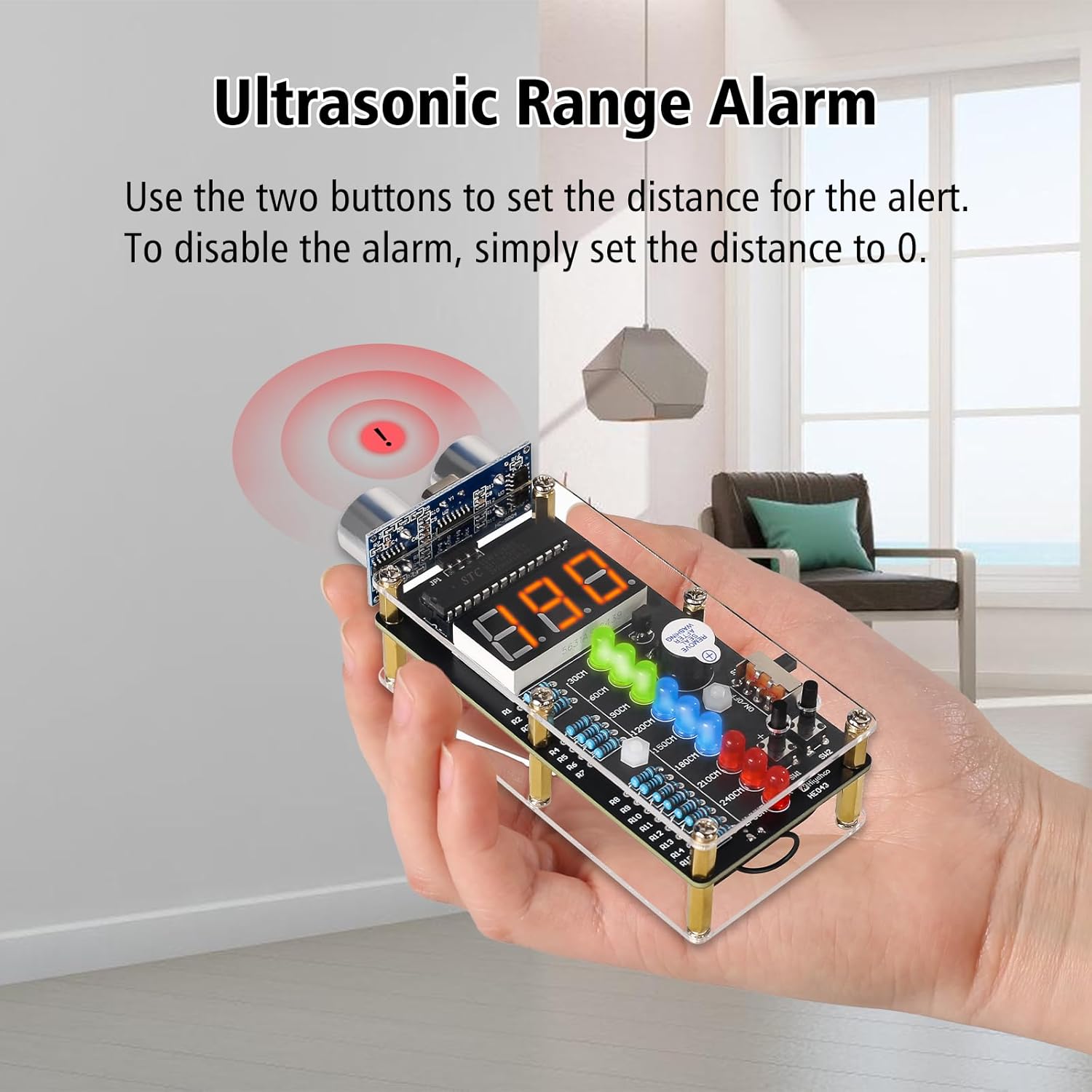
Figure 6.1: Ultrasonic Range Alarm in operation. This image demonstrates how to set the alarm distance using the two buttons, with a visual representation of the alarm being triggered when an object is too close.
6.2 LED Desk Lamp Operation
The LED desk lamp is designed for versatile use with adjustable features.
- Power On/Off: Use the power button located on the base to turn the lamp on or off.
- Adjustable Brightness: The lamp features adjustable brightness levels. Use the designated control (e.g., a dial or button) on the base to cycle through or select desired brightness settings.
- Flexible Gooseneck: Adjust the flexible gooseneck to direct the light precisely where needed.
- Phone Holder: The lamp base includes a built-in phone holder for convenience.

Figure 6.2: LED Desk Lamp demonstrating adjustable brightness. This series of images shows the lamp at different brightness settings, illustrating the user's ability to control the light intensity.
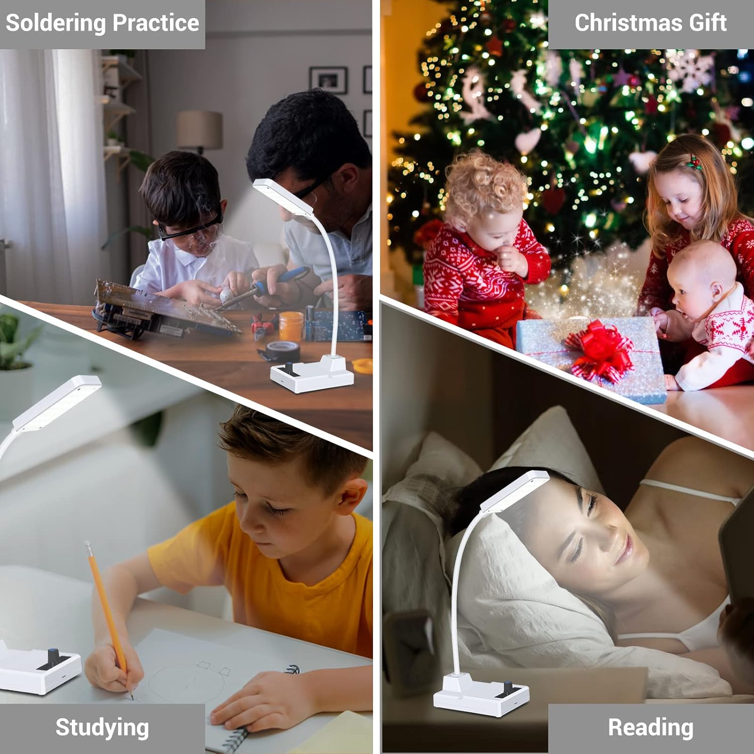
Figure 6.3: Various applications of the LED Desk Lamp. This collage shows the lamp being used for soldering practice, studying, and reading, highlighting its versatility.
7. Maintenance
- Keep both devices clean and free from dust. Use a soft, dry cloth for cleaning.
- Avoid exposing the devices to extreme temperatures or humidity.
- For the LED desk lamp, ensure the rechargeable battery is periodically charged to maintain its lifespan, even if not in regular use.
- Do not attempt to modify the internal circuitry beyond the intended DIY assembly.
8. Troubleshooting
If you encounter issues with your kit, consider the following common troubleshooting steps:
| Problem | Possible Cause | Solution |
|---|---|---|
| Ultrasonic Alarm not powering on. | Incorrect power connection, faulty power supply, or soldering error. | Check 5V power supply connection. Verify all power-related solder joints. Ensure the power switch is 'ON'. |
| Digital display shows incorrect readings or no reading. | HC-SR04 module not connected correctly, soldering error on display/module, or obstruction. | Inspect connections to the HC-SR04 module and digital tube. Ensure no obstructions are in front of the ultrasonic sensors. |
| LED Desk Lamp not turning on. | Battery discharged, power cable issue, or soldering error. | Charge the battery. Check the 5V power cable and adapter. Verify LED array and control board solder joints. |
| LED Desk Lamp brightness not adjusting. | Control mechanism (dial/button) not functioning, or soldering error. | Inspect the brightness control component and its solder connections. |
For issues not covered here, please refer to the detailed troubleshooting section in your physical manual or contact customer support.
9. Specifications
- Product Style: Ultrasonic Ranging Alarm DIY Kit and LED Desk Lamp Kit
- Ultrasonic Ranging Alarm:
- Measurement Range: 0 to 270 cm
- Display: 3-digit digital tube
- Indicators: Multiple LED lights for range indication
- Alarm: Audible beep when distance falls below set threshold
- Power Supply: 5V DC
- LED Desk Lamp:
- Features: Adjustable brightness, flexible gooseneck, phone holder
- Power Supply: 5V DC (USB) or built-in rechargeable battery
- Portability: Rechargeable battery for indoor/outdoor use
- ASIN: B0FF9WDNQF
- First Available: December 19, 2024
10. Warranty and Support
This product is a DIY kit intended for educational and hobbyist purposes. While every effort has been made to ensure component quality, successful operation depends on correct assembly. Please refer to the seller's return policy for information regarding defective components.
For technical support or inquiries, please contact the MiOYOOW customer service through the retailer's platform where the product was purchased. Keep your purchase receipt as proof of purchase.