1. Introduction
This manual provides detailed instructions for the installation, operation, and maintenance of your MGBIDMI 24V 4.2KW Solar Hybrid Inverter. Please read this manual thoroughly before installation and use to ensure proper function and safety. Retain this manual for future reference.
2. Important Safety Instructions
Read all instructions before installation and operation. Failure to follow these instructions may result in electric shock, fire, or severe injury.
- This device contains high voltage. Do not attempt to disassemble or repair it yourself. Refer all servicing to qualified personnel.
- Ensure proper grounding of the inverter.
- Install the inverter in a well-ventilated area, away from flammable materials, moisture, and direct sunlight.
- Disconnect all power sources (solar panels, battery, AC input) before performing any maintenance, wiring, or troubleshooting.
- Use appropriate personal protective equipment (PPE) during installation and maintenance.
- Ensure all wiring connections are tight and secure to prevent overheating and arcing.
3. Product Overview
3.1 Key Features
- Pure sine wave output for compatibility with various loads.
- Integrated MPPT solar charge controller and AC charger.
- Supports four charging modes: Solar priority, AC priority, Solar and AC mixed charging.
- Provides two output modes: Inverter and AC power.
- WiFi and GPRS connectivity for remote monitoring via iOS and Android applications.
- Compatible with lead-acid and lithium-ion battery types.
- High-definition LCD display for real-time system data and operating status.
- Multiple protection functions: overcurrent, overload, low voltage, overvoltage, short circuit, and reverse polarity.
- Durable aluminum alloy construction with efficient heat dissipation design.
3.2 Product Components
The MGBIDMI Solar Hybrid Inverter features a user-friendly interface and clearly labeled connection points. Refer to the image below for a visual guide to the main components and their functions.
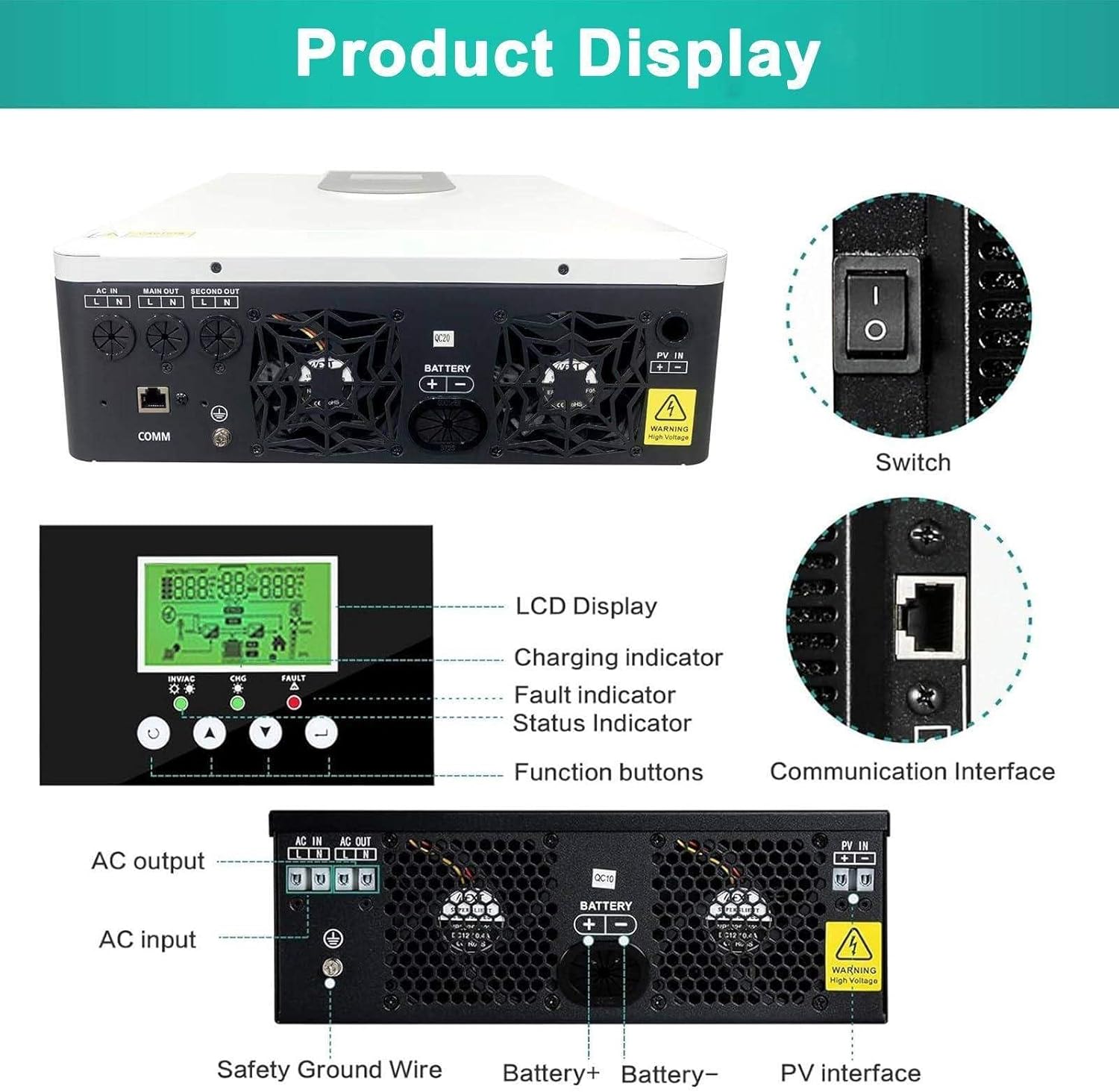
Image: Product Display. This image illustrates the various ports, the LCD display, charging indicator, fault indicator, status indicator, and function buttons on the MGBIDMI Solar Hybrid Inverter. Key connections include AC input, AC output, battery terminals, PV interface, communication interface, and safety ground wire.
- LCD Display: Shows important statistics such as status, mode, voltage, load power, and charge/discharge current.
- Function Buttons: Used for navigating menus and configuring settings on the LCD.
- LED Indicators: Provide quick visual status updates (e.g., charging, fault, status).
- AC Input/Output Terminals: For connecting to the utility grid and AC loads.
- Battery Terminals: For connecting to the external battery bank.
- PV Interface: For connecting to solar panels.
- Communication Interface: For WiFi/GPRS module and other communication protocols (e.g., RS485/232).
- Power Switch: To turn the inverter on or off.
4. Specifications
The following table outlines the key specifications for the MGBIDMI 24V 4.2KW Solar Hybrid Inverter.

Image: Model Specifications. This image provides a specification comparison, highlighting the MPPT voltage, current, PV range, and physical dimensions for different inverter models. For the 24V 4.2KW model, the MPPT voltage is 24V and MPPT current is 120A.
| Parameter | Value (24V 4.2KW Model) |
|---|---|
| Waveform | Pure Sine Wave |
| Input Voltage | 24V DC |
| Output Voltage | 220V AC |
| Rated Power | 4200W |
| Maximum Solar Charging Current | 120A |
| MPPT Voltage | 24V |
| PV Range | 60-450VDC |
| External Battery Type | Lead Acid / Lithium Battery |
| Dimensions (L*W*H) | 400mm * 355mm * 115mm |
| Manufacturer | MGBIDMI |
| ASIN | B0FF3B1TQH |
5. Setup and Installation
5.1 Mounting the Inverter
Choose a suitable location for mounting the inverter. The location should be:
- Indoors, protected from direct sunlight, rain, and dust.
- Well-ventilated to ensure proper heat dissipation.
- On a solid surface capable of supporting the inverter's weight.
- Away from flammable materials and corrosive gases.
5.2 System Connection Diagram
The following diagram illustrates a typical system connection for the MGBIDMI Solar Hybrid Inverter, integrating solar panels, battery, utility grid (ON Grid), and AC loads.

Image: System Connection. This diagram illustrates a household on/off-grid energy storage integrated system, showing how solar panels, the inverter, battery, utility grid, and various household appliances (AC output) are interconnected.
5.3 Wiring Instructions
All wiring should be performed by a qualified electrician. Ensure all power sources are disconnected before making any connections.
- Solar Panel Connection: Connect the positive and negative terminals of your solar array to the PV input terminals on the inverter. Observe correct polarity.
- Battery Connection: Connect the positive and negative terminals of your battery bank to the battery terminals on the inverter. Ensure correct polarity and use appropriately sized cables.
- AC Input Connection: Connect the utility grid (or generator) to the AC input terminals.
- AC Output Connection: Connect your AC loads (appliances) to the AC output terminals.
- Grounding: Connect the inverter's ground terminal to a reliable earth ground.
The inverter features a hidden installation wiring design. To access the wiring terminals, unscrew the screws to open the bottom cover. After installation, replace the bottom cover securely.

Image: Hidden Installation Wiring and Fan Cooling System. This image illustrates the hidden wiring compartment at the bottom of the inverter, which can be accessed by unscrewing the cover. It also shows the fan cooling system designed for efficient heat dissipation.
6. Operating Instructions
6.1 Initial Startup
- After all connections are securely made, turn on the battery breaker (if applicable).
- Turn on the solar panel breaker (if applicable).
- Turn on the AC input breaker (if applicable).
- Press the power switch on the inverter to turn it on. The LCD display will illuminate.
6.2 LCD Display and Feedback Buttons
The inverter is equipped with an HD LCD display and feedback buttons for user interaction. The display shows real-time operational data and allows for configuration of various parameters.
Image: LED Large Screen Feedback Button. This image highlights the high-definition display screen and the feedback buttons, which are used to navigate menus and configure settings on the inverter.
Use the navigation buttons (typically up, down, enter, escape) to browse through the display menus and adjust settings such as battery charging current, AC/solar charging priority, and load current priority.
6.3 Charging Modes
The inverter supports four distinct charging modes:
- Solar Priority: Solar power is prioritized for charging the battery and powering loads. AC power is used only when solar power is insufficient.
- AC Power Priority: AC power (utility grid) is prioritized for charging the battery and powering loads. Solar power is used as a secondary source.
- Solar and AC Mixed Charging: Both solar and AC power are used simultaneously to charge the battery and power loads, optimizing energy usage.
- Inverter Mode: The inverter draws power from the battery to supply AC loads.
6.4 Remote Monitoring (WiFi/App)
The inverter includes WiFi and GPRS functionality, allowing for intelligent monitoring via a smartphone application (available for iOS and Android). This feature enables users to monitor system data and operating status remotely.

Image: Smartphone App Intelligent Monitoring. This image shows a smartphone displaying the monitoring application for the inverter, demonstrating the WiFi and GPRS capabilities for remote system management and data viewing.
Refer to the separate WiFi/GPRS module manual for detailed instructions on connecting the inverter to your network and using the mobile application.
7. Maintenance
Regular maintenance ensures the longevity and optimal performance of your MGBIDMI Solar Hybrid Inverter.
- Cleaning: Periodically clean the exterior of the inverter with a dry cloth. Do not use liquid cleaners. Ensure ventilation openings are free from dust and debris.
- Connection Checks: Annually inspect all electrical connections (solar, battery, AC input/output) for tightness and signs of corrosion. Tighten any loose connections.
- Fan Cooling System: The inverter features a fan cooling system for efficient heat dissipation. Ensure the fan vents are not obstructed. Clean any dust accumulation from the fan blades and vents.
- Battery Inspection: Follow the maintenance guidelines for your specific battery type (lead-acid or lithium-ion).
8. Troubleshooting
If the inverter is not operating as expected, refer to the following basic troubleshooting steps. For complex issues, contact customer support.
- No Power/Display Off: Check all power connections (battery, solar, AC input). Ensure the power switch is ON. Verify battery voltage is within the operating range.
- No AC Output: Check AC output connections and circuit breakers. Verify that the inverter is not in a fault state (check LED indicators and LCD display for error codes). Ensure the load is not exceeding the inverter's rated power.
- Battery Not Charging: Check solar panel connections and output. Verify AC input is present if AC charging is enabled. Check battery health and connections.
- Overload/Over-temperature Fault: Reduce the connected load. Ensure adequate ventilation around the inverter. Clear any obstructions from the cooling fans.
- Error Codes: If an error code is displayed on the LCD, consult the specific error code section in the full product manual (if available) or contact customer support with the error code.
9. Warranty and Support
For warranty information, please refer to the documentation provided at the time of purchase or contact your vendor. For technical support, please reach out to MGBIDMI customer service.