1. Introduction
This manual provides essential information for the safe and efficient operation of your Generic 1.5KW Frequency Inverter, Model JLS-E-2S-1.5GB-4T. This device is designed to convert single-phase AC220V power to three-phase AC380V, offering variable frequency control for various industrial applications such as engraving machines, milling machines, and drilling machines. Please read this manual thoroughly before installation, operation, or maintenance.
2. Safety Information
WARNING: Read the user manual before operation. Risk of electrical shock. Wait 10 minutes after removing power before servicing.
- Ensure all wiring is performed by qualified personnel in accordance with local electrical codes.
- Always disconnect power before making any connections or performing maintenance.
- Do not operate the inverter in humid environments, or where water mist, droplets, or metal objects may fall into the unit, as this can cause short circuits.
- Verify input voltage (AC220V 50/60Hz) matches the inverter's specifications.
- Ensure proper grounding to prevent electrical shock.
- Do not touch internal components immediately after power disconnection, as residual voltage may be present.
3. Product Overview
The Generic 1.5KW Frequency Inverter features a robust design with a clear digital display and user-friendly control panel for precise operation.
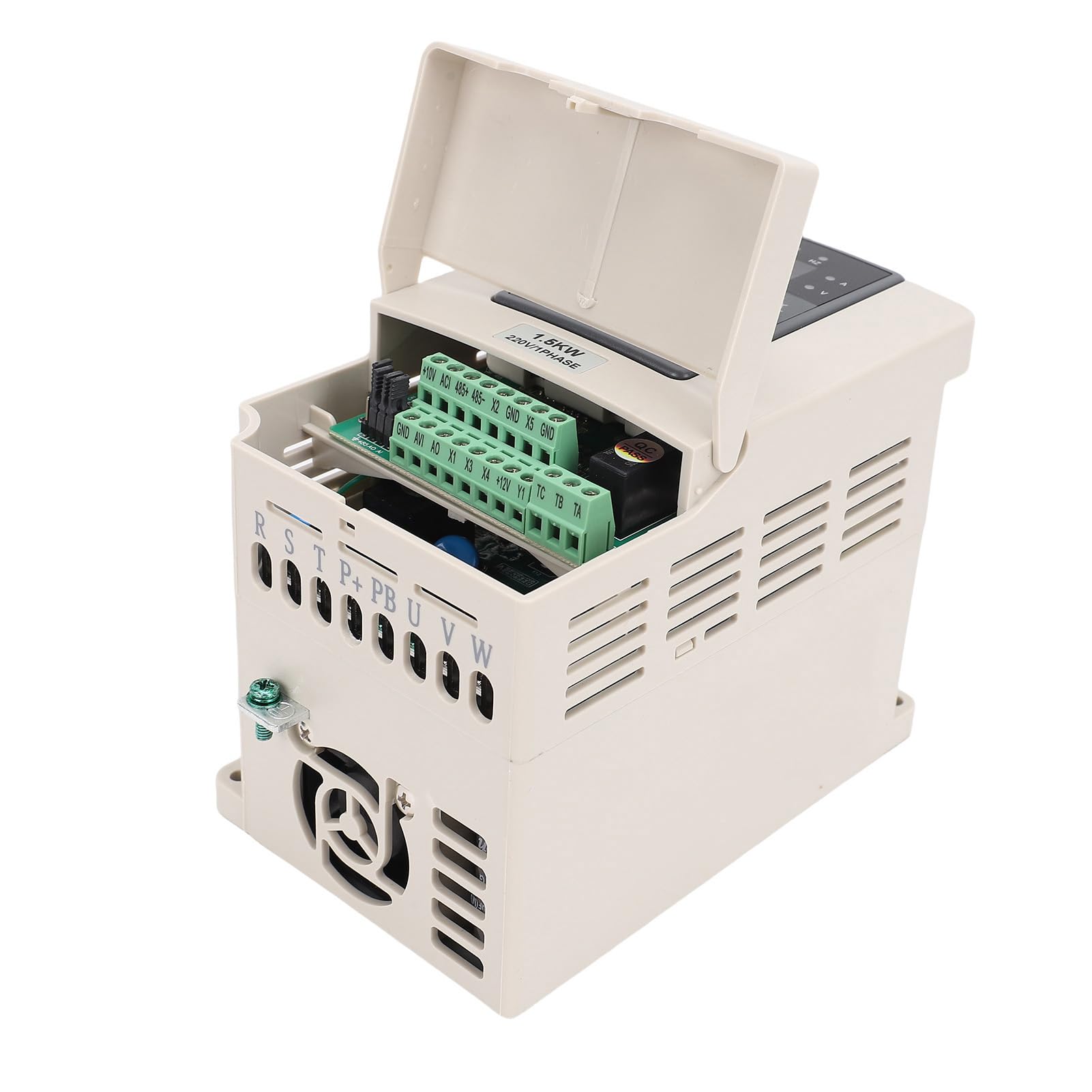
Figure 3.1: Front angled view of the 1.5KW Frequency Inverter, showing the control panel and warning label.
3.1 Control Panel
The control panel provides access to all operational parameters and displays real-time status.

Figure 3.2: Close-up view of the digital display and control buttons (PRG, MF, Run, Stop/Reset, directional arrows, Enter) and frequency adjustment knob.
- Digital Display: Shows frequency, voltage, current, and error codes.
- PRG (Program): Enters/exits parameter setting mode.
- MF (Multi-Function): Used for various functions depending on the mode.
- RUN: Starts the motor.
- STOP/RESET: Stops the motor or clears error states.
- Directional Arrows (Up/Down/Left/Right): Navigate menus and adjust parameter values.
- ENTER: Confirms selections or parameter changes.
- Frequency Adjustment Knob: Fine-tunes output frequency.
3.2 Wiring Terminals
The inverter features clearly labeled terminals for power input, motor output, and control signals.

Figure 3.3: Top view of the inverter with the terminal cover open, revealing control wiring connections (+10V, ACI, 485+, 485-, X2, GND, X5, GND, AVI, AO, X1, X3, X4, +12V, Y1, TC, TB, TA).

Figure 3.4: Rear view of the inverter, showing the main power input (R, S, T) and motor output (U, V, W) terminals, along with grounding point.
- R, S, T: Single-phase AC220V input terminals. (Note: Although labeled R, S, T, this model is for single-phase input to 3-phase output).
- U, V, W: Three-phase AC380V output terminals to the motor.
- GND: Grounding terminal.
- Control Terminals: Various terminals for external control signals, analog input/output, and RS485 communication (+10V, ACI, 485+, 485-, X2, GND, X5, GND, AVI, AO, X1, X3, X4, +12V, Y1, TC, TB, TA).
4. Specifications
| Parameter | Value |
|---|---|
| Model | JLS-E-2S-1.5GB-4T |
| Input Voltage | AC220V 50/60Hz (Single Phase) |
| Output Voltage | AC380V (Three Phase) |
| Output Frequency Range | 0-999Hz |
| Rated Power | 1.5KW |
| Output Current | 3A |
| Material | ABS, PC |
| Product Dimensions | 9.05 x 6.69 x 6.29 inches |
| Item Weight | 2.93 pounds |
| Communication Interface | RS485 |
5. Setup and Installation
5.1 Unpacking
Carefully remove the inverter from its packaging. Inspect for any signs of damage during transit. The package should contain: 1 x Single to 3 Phase Converter, 1 x Manual.
5.2 Mounting
- Mount the inverter vertically on a stable, non-flammable surface.
- Ensure adequate ventilation around the unit to prevent overheating. Maintain sufficient clearance from other equipment.
- Avoid mounting in direct sunlight, high temperature, high humidity, or dusty environments.
5.3 Wiring
All wiring must be performed by a qualified electrician. Ensure power is disconnected before wiring.
- Grounding: Connect the inverter's GND terminal to a reliable earth ground.
- Power Input: Connect the single-phase AC220V 50/60Hz power supply to the R and S (or T) input terminals.
- Motor Output: Connect the three-phase motor to the U, V, and W output terminals.
- Control Wiring (Optional): If using external control signals (e.g., start/stop buttons, potentiometers for speed control, RS485 communication), connect them to the appropriate control terminals as per your application requirements. Refer to the detailed wiring diagram in the full manual for specific connections.
Note: This inverter does not support external resistors. If your motor load is heavy, consider choosing an inverter with a higher power rating.
6. Operating Instructions
6.1 Basic Operation
- Power On: After completing all wiring and safety checks, apply power to the inverter. The digital display will illuminate.
- Set Frequency: Use the frequency adjustment knob or the directional arrow buttons to set the desired output frequency.
- Start Motor: Press the RUN button to start the motor. The display will show the current operating frequency and other parameters.
- Stop Motor: Press the STOP/RESET button to stop the motor.
6.2 Parameter Setting (PRG Mode)
The inverter has various parameters that can be adjusted to optimize performance for specific applications. Refer to the comprehensive parameter list in the full manual for detailed descriptions.
- Press the PRG button to enter parameter setting mode.
- Use the directional arrow buttons to navigate through parameter groups and individual parameters.
- Press ENTER to select a parameter for editing.
- Use the directional arrow buttons to adjust the parameter value.
- Press ENTER again to save the new value.
- Press PRG to exit parameter setting mode.
7. Maintenance
- Cleaning: Regularly clean the exterior of the inverter with a soft, dry cloth. Do not use liquid cleaners or solvents.
- Ventilation: Ensure cooling vents are free from dust and obstructions to maintain proper airflow.
- Connections: Periodically check all wiring connections for tightness and signs of corrosion.
- Environment: Maintain the operating environment within specified temperature and humidity ranges.
8. Troubleshooting
This section provides solutions to common issues. For complex problems, contact technical support.
| Problem | Possible Cause | Solution |
|---|---|---|
| Inverter does not power on. | No input power; faulty wiring; internal fuse blown. | Check power supply; verify wiring connections; consult a technician for fuse replacement. |
| Motor does not start. | Incorrect parameters; motor wiring error; overload. | Check motor parameters (frequency, voltage); verify motor wiring (U, V, W); reduce load or check motor for issues. |
| Overload error displayed. | Motor drawing excessive current; inverter undersized for load. | Reduce motor load; check motor for mechanical issues; consider a higher-rated inverter if load is consistently heavy. |
| Abnormal noise from inverter or motor. | Loose connections; motor issues; incorrect frequency settings. | Check all wiring connections; inspect motor; verify frequency settings. |
9. Warranty and Support
For warranty information and technical support, please refer to the documentation provided with your purchase or contact your vendor. Keep your purchase receipt for warranty claims.


