Introduction
This manual provides essential information for the safe and effective installation, operation, and maintenance of your new gas oven range ignitor. This universal ignitor is designed to restore reliable ignition for your oven, addressing issues such as slow heating or complete ignition failure. Please read these instructions thoroughly before proceeding with installation or use.
The ignitor operates at 120V and draws 3.2-3.6A. It features a durable ceramic base and an 8-inch wire length, ensuring high durability and consistent performance.
Safety Information
- DANGER: Before attempting any installation or maintenance, ensure the gas supply to the appliance is turned off and the appliance is disconnected from the electrical power supply. Failure to do so can result in serious injury, electric shock, gas leak, fire, or death.
- Always wear appropriate personal protective equipment, such as gloves and safety glasses, during installation.
- If you are unsure about any step, consult a qualified appliance technician.
- This ignitor is designed for use only with Eaton 4100 Series Automatic Valves. Verify compatibility with your oven's valve system before installation.
- After installation, check for gas leaks using a soap and water solution. Never use an open flame to check for leaks.
- Keep children and pets away from the work area.

Image: The ignitor showing a critical warning label regarding compatibility with Eaton 4100 Series Automatic Valves.
Package Contents
Verify that all components are present and undamaged before beginning installation.
- 1 x Gas Oven Range Ignitor
- Wire Connectors
- Installation Instructions (this manual)
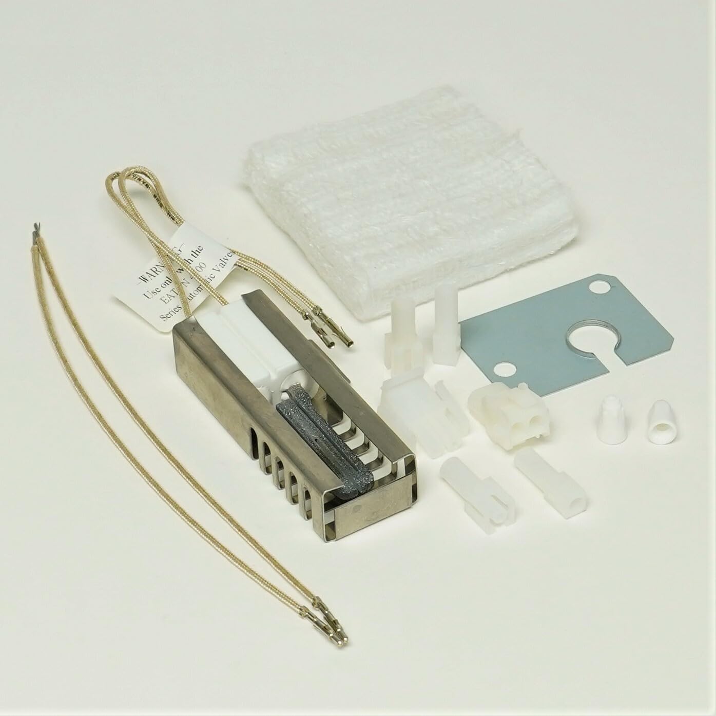
Image: The main gas oven range ignitor unit.

Image: Various wire connectors included for installation.
Specifications
| Product Type | Gas Oven Range Ignitor |
| Compatibility | Magic Chef models: 4100PRA-K, 4100PRW-K, 4121WRA, 41EA-14K, 41EA-2KLW, 41EA-2KW, and others listed in the product description. Compatible with Eaton 4100 Series Automatic Valves. |
| Voltage | 120V |
| Current Draw | 3.2-3.6A |
| Dimensions | 3.7 x 0.5 x 0.5 inches |
| Weight | 0.2 lbs |
| Base Material | Ceramic |
| Wire Length | 8 inches |
| Part Number | 79075602100 |
| Manufacturer | Van Anh Appliance Hub |

Image: Side view of the ignitor, highlighting its ceramic base and heating element.
Setup and Installation
This section outlines the general steps for replacing a gas oven range ignitor. Specific procedures may vary slightly depending on your oven model. Always refer to your oven's service manual for detailed instructions.
- Preparation:
- Ensure the oven is completely cool.
- Turn off the gas supply to the oven.
- Disconnect the oven from the electrical power supply (unplug or turn off the circuit breaker).
- Gather necessary tools: screwdriver set, wire cutters/strippers, pliers, and a flashlight.
- Access the Ignitor:
- Open the oven door and remove oven racks.
- Locate and remove the oven bottom panel and/or burner cover to expose the ignitor and burner assembly. This usually involves removing a few screws.

Image: Diagram illustrating typical locations for an appliance's model number, which can help in locating internal components.
- Disconnect the Old Ignitor:
- Carefully disconnect the wires leading to the old ignitor. Note their position for reinstallation.
- Unscrew and remove the old ignitor from its mounting bracket. Ignitors are fragile; handle with care.
- Install the New Ignitor:
- Attach the new ignitor to the mounting bracket using the provided screws. Ensure it is securely fastened and positioned correctly relative to the burner tube.
- Connect the new ignitor's wires to the oven's wiring harness using the included wire connectors. Ensure connections are secure and insulated.

Image: Close-up view of the ignitor's wire terminals, ready for connection.

Image: The mounting plate and ceramic insulators, which may be used during installation.
- Reassembly and Testing:
- Replace the oven bottom panel and/or burner cover.
- Restore the electrical power supply and turn on the gas supply.
- Check for gas leaks around connections using a soap and water solution. Bubbles indicate a leak. If a leak is detected, turn off the gas immediately and tighten connections or seek professional help.
- Test the oven by setting it to bake. Observe if the ignitor glows and ignites the gas burner within 30-60 seconds.
Operating Principles
The gas oven range ignitor is a glow-bar type ignitor. When the oven is turned on, electrical current flows through the ignitor, causing it to heat up and glow bright orange. This heat serves two purposes:
- It provides the necessary heat to ignite the gas flowing from the burner.
- As the ignitor heats, its electrical resistance decreases, allowing more current to flow through a safety valve. Once sufficient current is detected by the safety valve, it opens, allowing gas to flow to the burner, where it is then ignited by the hot ignitor.
A properly functioning ignitor will glow brightly and ignite the gas within a minute. If the ignitor glows but the gas does not ignite, or if it takes an unusually long time, the ignitor may be weak and require replacement.
Maintenance
The gas oven range ignitor is generally a sealed unit and requires minimal maintenance. However, periodic inspection can help ensure its longevity and proper function.
- Visual Inspection: Periodically, with the power and gas off, inspect the ignitor for any visible cracks, damage, or excessive carbon buildup. A healthy ignitor should appear intact.
- Cleaning: If there is light dust or debris, gently brush it away with a soft, dry brush. Avoid using any liquids or abrasive cleaners on the ignitor.
- Connection Check: Ensure that the wire connections remain secure and free from corrosion.
Do not attempt to repair a damaged ignitor. If damage is observed or performance degrades, replace the unit.
Troubleshooting
If your oven is experiencing ignition problems, consider the following troubleshooting steps related to the ignitor. Always ensure safety precautions (gas and power off) before inspecting components.
| Problem | Possible Cause | Solution |
|---|---|---|
| Oven does not heat, ignitor does not glow. | No power to the oven, faulty ignitor, loose wiring connection. | Check oven's power supply. Inspect ignitor wiring for secure connections. If power is present and connections are good, the ignitor is likely faulty and needs replacement. |
| Ignitor glows but gas does not ignite, or ignites slowly. | Weak ignitor, gas supply issue, faulty gas valve. | A weak ignitor may not draw enough current to open the gas valve fully or quickly enough. Replace the ignitor. Verify gas supply to the oven is on. If the problem persists after ignitor replacement, consult a qualified technician for gas valve inspection. |
| Oven heats intermittently. | Intermittent electrical connection, ignitor nearing end of life. | Check all electrical connections to the ignitor. If connections are secure, the ignitor may be failing and should be replaced. |
If these troubleshooting steps do not resolve the issue, it is recommended to contact a qualified appliance repair technician.
Warranty Information
This Gas Oven Range Ignitor comes with a 1-Year Manufacturer's Warranty. This warranty covers defects in materials and workmanship under normal use. It does not cover damage resulting from improper installation, misuse, accident, or unauthorized repairs.
For warranty claims or further details, please retain your proof of purchase and contact the manufacturer or seller.
Support and Contact
For technical assistance, questions regarding compatibility, or support with your Gas Oven Range Ignitor, please contact the manufacturer:
Manufacturer: Van Anh Appliance Hub
Please have your product model number and purchase information ready when contacting support.


