1. Introduction
This manual provides comprehensive instructions for the installation, operation, and maintenance of your Mangood 12V-36V 4-Channel Wireless Control Relay Switch. This device is designed for controlling various electrical applications such as lights, motors, fans, and doors using a 433MHz wireless remote control system. Please read this manual thoroughly before use to ensure proper functionality and safety.
2. Product Overview
The Mangood 4-Channel Wireless Control Relay Switch system includes a receiver module and two remote control transmitters. It operates within a DC 12V-36V range and offers multiple working modes for versatile control.
2.1 Components
- 1x 4-Channel Switch Receiver: The main control unit that receives signals from the remote and operates the connected devices.
- 2x Remote Control Transmitters: Handheld devices used to send wireless commands to the receiver. Each transmitter includes a 23A battery.

Figure 1: Mangood 4-Channel Wireless Control Relay Switch Receiver and two Remote Transmitters. The image displays the white receiver module with its internal circuit board visible, alongside two matching white remote controls, each featuring four buttons labeled A, B, C, and D.
2.2 Key Features
- Wide Voltage Compatibility: Operates with DC 12V-36V input and can control loads from 1V to 250V.
- 4-Channel Control: Independently control up to four different circuits simultaneously.
- Multiple Work Modes: Supports Momentary, Toggle (Self-lock), Inter-lock (Latched), and various combinations of these modes.
- 433MHz Wireless Frequency: Provides stable signal transmission.
- Extended Range: Up to 100 meters (open/ideal conditions) with signal penetration through walls, floors, and doors.
- Easy Pairing: Simple learning button procedure for adding and removing remote controls.
- Durable Construction: Features an ABS shell for high-temperature resistance and non-flammability, along with flame-retardant terminals.

Figure 2: Various applications for the wireless control relay switch. Examples include remote garage door operation, motor control, agro-farming equipment, automated industrial equipment, remote curtain control, remote lighting, lift machinery, and farm irrigation systems.
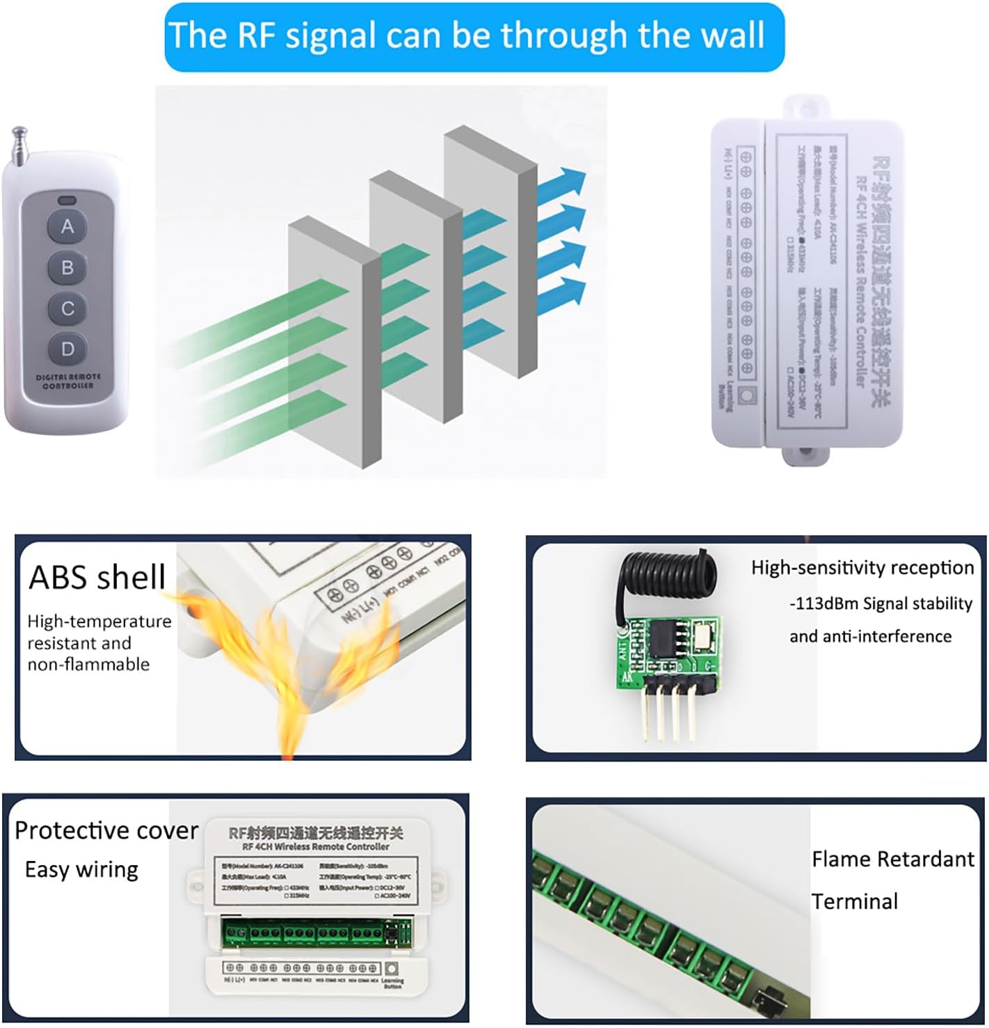
Figure 3: Visual representation of key features including RF signal penetration through walls, the durable ABS shell, high-sensitivity reception for signal stability, protective cover for easy wiring, and flame-retardant terminals.
3. Specifications
| Feature | Specification |
|---|---|
| Receiver Working Voltage | DC 12V - 36V |
| Output Way | Momentary / Toggle / Latched / Momentary+Toggle combinations |
| Maximum Load Current | 10A |
| Relay Load Capacity | 10A/250V AC, 10A/125V AC, 10A/30V DC, 10A/28V DC |
| Operating Frequency | 433MHz |
| Frequency Distance (Transmitter) | Up to 100 meters (open/ideal conditions) |
| Transmitter Operating Voltage | DC 12V (23A battery included) |
| Transmitter Operating Current | 30mA |
| Working Temperature | -40°C to +70°C |
| Receiver Dimensions | 8.8 x 6 x 3 cm (approx. 3.46 x 2.36 x 1.18 inches) |
| Product Dimensions | 5.12 x 2.6 x 1.02 inches (overall package/product) |
| Item Weight | 0.1 ounces |
| Max Supported Devices | 20 (remote controls) |

Figure 4: Detailed dimensions of the receiver module and the remote control transmitter. The receiver measures approximately 132mm in length, 66mm in width, and 26mm in height. The remote control measures approximately 9.7cm in length (excluding antenna) and 3.8cm in width, with an antenna extending to 18cm.
4. Setup and Installation
Before installation, ensure the power supply is disconnected to prevent electrical shock. This device is designed for use by individuals familiar with basic electrical wiring.
4.1 Receiver Components

Figure 5: Internal view of the receiver module, highlighting key components such as the relays, wiring terminals, antenna, and the 'Learn' button for programming remote controls.
4.2 Wiring Diagrams
The receiver supports various wiring configurations depending on the application and desired control voltage. Always ensure correct polarity and voltage matching for your devices.
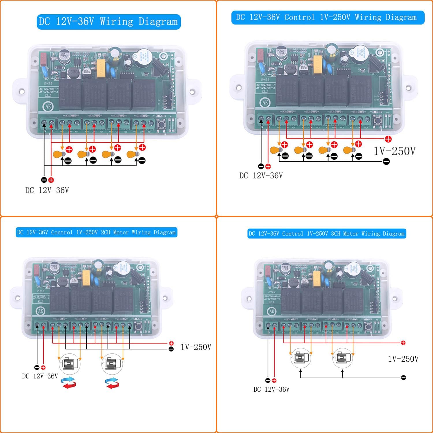
Figure 6: Wiring diagrams for the Mangood 4-Channel Wireless Control Relay Switch. This image illustrates four common wiring scenarios: DC 12V-36V power input, controlling 1V-250V loads with DC 12V-36V power, controlling 2-channel motors with 1V-250V loads, and controlling 3-channel motors with 1V-250V loads. Each diagram shows the input power connections and output connections to various devices, indicating positive and negative terminals.
- DC 12V-36V Wiring: Connect your DC power source (12V-36V) to the input terminals. The output terminals can then switch devices operating within this voltage range.
- DC 12V-36V Control 1V-250V Wiring: This configuration allows the 12V-36V receiver to switch higher or lower voltage AC/DC loads (1V-250V) by utilizing the relay's isolated contacts.
- Motor Control Wiring (2-Channel & 3-Channel): Specific diagrams are provided for controlling motors, often requiring forward and reverse functionality, by utilizing multiple relay channels.
Warning: Incorrect wiring can damage the device or connected equipment, and poses a risk of electrical shock. If you are unsure, consult a qualified electrician.
5. Operation
5.1 Work Modes
The receiver supports several operational modes, which determine how the relay channels respond to remote control button presses. These modes are configured during the learning process.
- Momentary: The relay is active only while the remote button is pressed and held. Releasing the button deactivates the relay.
- Toggle (Self-lock): Pressing the remote button activates the relay. Pressing the same button again deactivates the relay.
- Inter-lock (Latched): Pressing one button activates its corresponding relay and deactivates any other active relays within the inter-locked group. For example, if buttons 1-4 are inter-locked, pressing button 1 activates relay 1, and pressing button 2 deactivates relay 1 and activates relay 2. Only one relay can be active at a time in an inter-locked group.
- Combined Modes: The receiver also supports combinations like "2 Momentary + 2 Inter-lock", "2 Momentary + 2 Self-lock", and "2 Inter-lock + 2 Self-lock", allowing for flexible control schemes.
5.2 Programming Remote Controls (Learning Mode)
To pair a remote control with the receiver and set its work mode, follow these steps:
- Select Work Mode: Press the 'Learn' button on the receiver a specific number of times corresponding to the desired work mode:
- 1 time for Momentary mode
- 2 times for Toggle (Self-lock) mode
- 3 times for Inter-lock (Latched) mode
- 4 times for 2 Momentary + 2 Inter-lock mode
- 5 times for 2 Momentary + 2 Self-lock mode
- 6 times for 2 Inter-lock + 2 Self-lock mode
- Pair Remote: After pressing the 'Learn' button the required number of times, the indicator light on the receiver will illuminate. Immediately press any control button on your remote control for 1-3 seconds. The indicator light will flash and then turn off, indicating successful pairing.
Repeat this process for each remote control you wish to pair, or if you need to change the work mode for an existing remote.
5.3 Deleting Remote Controls
To remove all paired remote controls from the receiver's memory:
- Press and hold the 'Learn' button on the receiver for approximately 8 seconds. The indicator light will flash and then turn off, confirming that all remote controls have been deleted.
6. Maintenance
6.1 Remote Control Battery Replacement
The remote control transmitters are powered by a 12V 23A battery. If the remote's range decreases or it stops responding, the battery may need replacement. To replace the battery:
- Carefully open the remote control casing.
- Remove the old 23A battery.
- Insert a new 12V 23A battery, ensuring correct polarity.
- Close the remote control casing securely.
Dispose of old batteries according to local regulations.
7. Troubleshooting
- Remote not responding:
- Check the remote control battery. Replace if necessary.
- Ensure the receiver is powered correctly (DC 12V-36V).
- Verify that the remote is paired with the receiver. If not, follow the programming instructions in Section 5.2.
- Check for strong interference sources (e.g., other 433MHz devices, large metal objects) that might block the signal.
- Short operating range:
- Replace the remote control battery.
- Ensure the receiver's antenna is unobstructed and extended.
- Minimize obstacles between the remote and receiver.
- Relay not switching:
- Confirm the wiring to the load is correct and secure.
- Ensure the load's voltage and current do not exceed the relay's specifications (10A, 1V-250V).
- Check the selected work mode (Momentary, Toggle, Inter-lock) to ensure it matches your intended operation.
8. Safety Information
- Always disconnect power before performing any wiring or maintenance.
- Ensure all wiring connections are secure and insulated to prevent short circuits.
- Do not exceed the maximum load current or voltage ratings of the receiver.
- Keep the device away from water, excessive heat, and corrosive environments.
- This device is not intended for life-support systems or applications where malfunction could lead to severe injury or property damage.
- Dispose of electronic waste and batteries responsibly according to local regulations.
9. Warranty and Support
Specific warranty information for the Mangood 12V-36V 4-Channel Wireless Control Relay Switch is not provided in this manual. For warranty details, technical support, or service inquiries, please contact the manufacturer or your point of purchase. Please retain your proof of purchase for any warranty claims.