PG Power Guard PG 500
Power Guard PG 500 Voltage Stabilizer User Manual
Brand: PG Power Guard | Model: PG 500
1. Introduction
The Power Guard PG 500 Voltage Stabilizer is designed to protect your valuable 2.0 Ton Inverter, Non-Inverter, Split, and Window Air Conditioners from harmful voltage fluctuations. Manufactured with high-quality components in India, this stabilizer ensures stable power delivery, enhancing the lifespan and performance of your AC unit. It features an intelligent design with advanced protection mechanisms to safeguard your appliance against common electrical issues.

2. Product Features
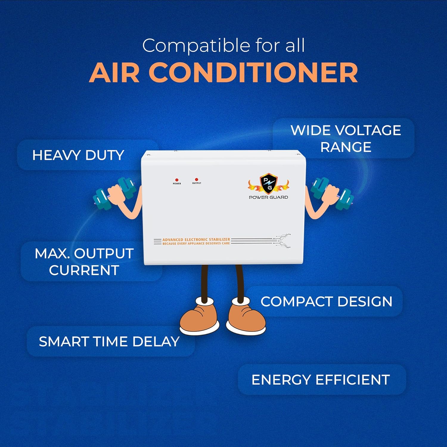
The PG 500 Voltage Stabilizer incorporates several key features to ensure optimal protection and performance for your air conditioner:
- Wide Input Voltage Range (170V–280V): This stabilizer effectively manages a broad spectrum of voltage fluctuations, providing a consistent and safe power supply to your AC, even in areas with unstable electricity.
- Advanced Thermal Overload Protection: In the event of overheating or an electrical fault, the stabilizer automatically cuts off power, preventing potential damage to both the stabilizer and the connected AC unit.
- Intelligent Time Delay System: This crucial feature protects the AC compressor by introducing a delay before restarting power after a voltage drop or power outage. This allows the compressor to stabilize, preventing wear and tear.
- Wall-Mountable & Compact Design: The stabilizer is designed for easy wall installation, saving space and integrating seamlessly into your home environment.
- Heavy Duty & Energy Efficient: Built to handle the demands of 2.0 Ton ACs, the PG 500 is also designed to operate efficiently, minimizing power consumption.
- Made in India: Proudly manufactured in India, ensuring quality craftsmanship and local support.

3. Installation Guide
The Power Guard PG 500 is designed for easy wall-mounting. Follow these steps for a secure installation:
- Step 1: Locate a Suitable Place: Choose a flat, vertical surface on the wall near your air conditioner's power outlet. Ensure the location is dry, well-ventilated, and away from direct sunlight or heat sources.
- Step 2: Mark Drilling Holes: Hold the stabilizer against the wall at the desired height. Using a pencil, mark the positions for the drilling holes. The standard distance between the top mounting holes is approximately 150 mm.
- Step 3: Drill the Holes: Using an appropriate drill bit (hole diameter less than 7 mm), drill holes at the marked positions.
- Step 4: Insert Plastic Plugs: Gently tap the provided plastic wall plugs into the drilled holes until they are flush with the wall surface.
- Step 5: Mount the Stabilizer: Insert the steel screws into the plastic plugs, leaving a small portion of the screw head exposed. Carefully align the stabilizer's keyhole slots on its back panel with the screw heads and slide the stabilizer down to secure it in place. Ensure it is firmly seated.


4. Operating Instructions
The Power Guard PG 500 Voltage Stabilizer operates automatically to protect your AC. Once installed and connected, it requires minimal user intervention.
- Power On: Connect the stabilizer to the main power supply and then connect your AC unit to the stabilizer's output. The "POWER" indicator light on the front panel will illuminate, indicating that the stabilizer is receiving power.
- Voltage Regulation: The stabilizer will automatically detect and regulate incoming voltage within its operational range (170V-280V). If the voltage goes outside this range, the stabilizer will cut off power to protect the AC.
- Time Delay: Upon initial power-on or after a power interruption, the intelligent time delay system will activate. The "OUTPUT" indicator light will typically blink or remain off for a few seconds (usually 3-5 minutes, depending on the model) before providing stable power to the AC. This delay is crucial for compressor safety.
- Output Indicator: Once stable power is supplied to the AC, the "OUTPUT" indicator light will illuminate steadily.
- Protection Modes: The stabilizer continuously monitors voltage. In case of high voltage, low voltage, or thermal overload, it will automatically disconnect the power to the AC to prevent damage. Once the voltage returns to a safe range, and after the time delay, it will automatically restore power.

5. Maintenance
The Power Guard PG 500 Voltage Stabilizer is designed for zero maintenance, offering maximum safety and reliability. To ensure its longevity and optimal performance, consider the following:
- Keep Clean: Periodically wipe the exterior of the stabilizer with a soft, dry cloth to remove dust. Do not use liquid cleaners or abrasive materials.
- Ensure Ventilation: Make sure the stabilizer's ventilation openings are not blocked to allow for proper heat dissipation.
- Avoid Overloading: Ensure that the connected AC unit does not exceed the stabilizer's specified capacity (2.0 Ton AC).
- Check Connections: Occasionally check that the power cables are securely connected to both the stabilizer and the AC unit.

6. Troubleshooting
If you encounter issues with your Power Guard PG 500 Voltage Stabilizer, consider the following basic troubleshooting steps:
- No Power Indicator:
- Check if the main power supply to the stabilizer is active.
- Ensure the power cord is securely plugged into both the wall outlet and the stabilizer.
- AC Not Receiving Power (Output Indicator Off/Blinking):
- The stabilizer might be in time delay mode after a power fluctuation. Wait for the delay period to complete.
- The input voltage might be outside the 170V-280V operating range. The stabilizer will cut off power to protect the AC. Wait for voltage to normalize.
- Check if the AC unit is properly connected to the stabilizer's output.
- If the stabilizer has tripped due to thermal overload, it will automatically reset once it cools down. Ensure proper ventilation.
- Unusual Noise or Smell:
- Immediately disconnect the stabilizer from the power supply.
- Contact customer support for assistance. Do not attempt to open or repair the unit yourself.
For issues not resolved by these steps, please refer to the Warranty and Support section.
7. Specifications
| Attribute | Detail |
|---|---|
| Manufacturer | Power Guard Industires Private Limited |
| Item Model Number | PG 500 |
| ASIN | B0FDBB82HR |
| Item Weight | 3 kg 380 g |
| Item Dimensions (LxWxH) | 28 x 10.5 x 19 Centimeters |
| Net Quantity | 1.0 Set |
| Generic Name | Voltage Stabilizer |
| Input Voltage Range | 170V to 280V |
| Compatibility | 2.0 Ton Inverter, Non-Inverter, Split & Window ACs |
8. Warranty and Support
The Power Guard PG 500 Voltage Stabilizer comes with a comprehensive 5-Year Onsite Warranty, providing peace of mind and reliable after-sales support.
For any warranty claims, technical assistance, or product inquiries, please contact Power Guard customer support:
- Toll-Free Contact: 18001201774
- WhatsApp Support: 9056677752
- Email Support: Support@powerguardonline.com
Please retain your purchase receipt for warranty validation.
9. What's in the Box
Upon opening the package, you will find the following items:
- 1 x Power Guard PG 500 Voltage Stabilizer Unit
- Mounting Screws and Wall Plugs
- User Manual (this document)
- Warranty Card

Related Documents - PG 500
 |
IRO Chrono X4 Spare Parts List and Exploded View Detailed spare parts list and exploded view diagram for the IRO Chrono X4 (models 8624/8724) 170V, including part numbers, descriptions, and model-specific information. |
 |
ROJ Luna X4 170V Exploded View and Spare Parts List Detailed exploded view and comprehensive spare parts list for the ROJ Luna X4 170V feeder, including part numbers, descriptions, and compatibility notes for models 8027 and 8127. |
 |
ROJ Chrono X3 6124/6024-41-XXH Feeder Spare Parts List and Exploded View Comprehensive spare parts list and exploded view for the ROJ Chrono X3 6124/6024-41-XXH electronic component feeder. Includes part numbers, descriptions, and remarks for all components. |
 |
Luna X3 170V Spare Parts List and Exploded View Comprehensive spare parts list and exploded view for the IRO AB Luna X3 170V feeder models (7027 and 7127), detailing part numbers, descriptions, and model applicability. |
 |
CITEL MJ8-xxx Überspannungsschutz: Installationsanleitung und Technische Daten Umfassende Installationsanleitung für CITEL MJ8-xxx Überspannungsschutzgeräte. Enthält technische Daten, Anwendungsbeispiele, Montagehinweise und Sicherheitsinformationen für Ethernet-, PoE- und Telekommunikationsleitungen. |
 |
MJJC LED Power Supply User Manual - 60W to 400W Models Comprehensive user manual for MJJC LED power supplies, detailing specifications, features, and wiring diagrams for models ranging from 60W to 400W with 12V and 24V DC outputs. Includes input voltage, output current, dimensions, and connection instructions for various configurations. |
Ask a question about this manual
Ask about setup, troubleshooting, compatibility, parts, safety, or missing instructions. Manuals+ will review the question and use this page’s manual context to help answer it.