Introduction
This manual provides instructions for the installation, operation, and maintenance of your Binardat 12-Port Gigabit PoE Switch, Model 12x1G PoE. Please read this manual thoroughly before using the device to ensure proper setup and functionality. Keep this manual for future reference.
Product Overview

Image: This image provides an overview of the Binardat 12-Port Gigabit PoE Switch, showing its 8 PoE ports, 2 RJ45 uplink ports, and 2 SFP uplink ports. Key features like full Gigabit ports, IEEE 802.3af/at support, plug and play, fanless design, port-based VLAN, fiber connectivity, and wall mount capability are highlighted.
Key Features
- 12 Gigabit Ports: Includes 8 Gigabit PoE+ ports, 2 Gigabit RJ45 uplink ports (non-PoE), and 2 Gigabit SFP uplink ports. All ports support 10/100/1000 Mbps auto-negotiation.
- PoE+ Standard Compliance: Supports IEEE 802.3af/at standards, automatically detecting and providing power to compatible Power Devices (PDs).
- High Power Budget: Features an internal 135W power supply, with a maximum of 30W output per PoE port. Output voltage range is 44-57V. Note: Does not support 24V passive PoE.
- Unmanaged Plug and Play: No configuration required. Simply connect the power and Ethernet cables for immediate operation.
- Extended Function (Port-based VLAN): Data traffic on PoE ports 1-8 can be isolated, communicating only with uplink ports 9-12. This reduces network overload, increases bandwidth utilization, and enhances network security.
- Durable Design: Housed in a robust metal casing, designed for fanless and quiet operation.
- Installation Flexibility: Supports wall mounting.
- Advanced Protection: Includes 4KV lightning protection.
Package Contents
- Binardat 12-Port Gigabit PoE Switch (Model 12x1G PoE)
- Power Cable
- User Manual (this document)
Physical Description
Front Panel Layout
The front panel of the switch features all network ports and LED indicators for status monitoring.

Image: Detailed view of the switch's front panel, showing 8 PoE ports, 2 RJ45 uplink ports, 2 SFP ports, and LED indicators.
- PoE Ports (1-8): 8 x 1Gbps ports supporting IEEE 802.3af/at PoE+.
- RJ45 Uplink Ports (9-10): 2 x 1Gbps non-PoE uplink ports.
- SFP Uplink Ports (11-12): 2 x 1Gbps SFP ports for fiber optic connections.
- DIP Switch: Located on the left side.
- Left Position (VLAN Mode): Enables port-based VLAN, isolating data traffic between PoE ports 1-8.
- Right Position (Default Mode): Standard operation, all ports can communicate freely.
- LED Indicators:
- PWR (Power Indicator): Red when power is on.
- PoE Ports (1-8) Link/Act: Green for 1000Mbps link/activity, Yellow for 10/100Mbps link/activity.
- RJ45 Uplink Ports (9-10) Link/Act: Green for 1000Mbps link/activity.
- SFP Uplink Ports (11-12) Link/Act: Green for 1000Mbps link/activity.
Rear Panel Layout
The rear panel contains the AC power input port.
Image: The rear panel showing the AC power input port. The built-in power supply is 52V/2.6A (135W).
- AC Input Port: Connect the provided power cable here. The switch has a built-in power supply of 52V/2.6A (135W).
Setup and Installation
The Binardat 12-Port Gigabit PoE Switch is designed for plug-and-play operation, requiring minimal setup.
Step-by-Step Installation
- Placement: Choose a suitable location for the switch. Ensure it is on a stable surface or mounted securely to a wall. Maintain adequate ventilation around the device.

Image: The switch can be mounted on a wall for flexible placement.
- Power Connection: Connect the provided power cable to the AC input port on the rear panel of the switch, then plug the other end into a standard AC power outlet. The PWR LED on the front panel should illuminate red.
- Network Device Connection:
- For PoE Devices (e.g., IP Cameras, Wireless Access Points, IP Phones): Connect these devices to any of the 8 PoE ports (1-8) using standard Ethernet cables. The switch will automatically detect and provide power to compliant PoE devices.
- For Non-PoE Devices (e.g., Routers, Computers, NVRs): Connect these devices to the uplink ports (9-10 RJ45 or 11-12 SFP) using standard Ethernet cables or SFP modules. These ports do not provide PoE power but transmit data.

Image: Diagram illustrating how to connect PoE devices (IP Camera, Wireless AP, IP Phone) to PoE ports and non-PoE devices (Router, Computer, NVR) to uplink ports.
- Verify Connections: Check the Link/Act LEDs for each connected port. A green LED indicates a 1000Mbps link, while a yellow LED indicates a 10/100Mbps link. Blinking LEDs indicate data activity.
Operating Instructions
Basic Operation
Once connected, the switch operates automatically. It is an unmanaged switch, meaning no software configuration is required. Data and power (for PoE devices) are transmitted as soon as devices are connected.
Using the DIP Switch (VLAN Mode)
The DIP switch on the front panel allows you to enable or disable the Port-based VLAN function.
- Default Mode (DIP switch to the right): All ports (1-12) can communicate with each other. This is the standard operating mode for a typical network.
- VLAN Mode (DIP switch to the left): When enabled, PoE ports 1-8 are isolated from each other. Each of these ports can only communicate with the uplink ports (9-12). This mode is useful for enhancing security and preventing broadcast storms in surveillance systems or large networks.
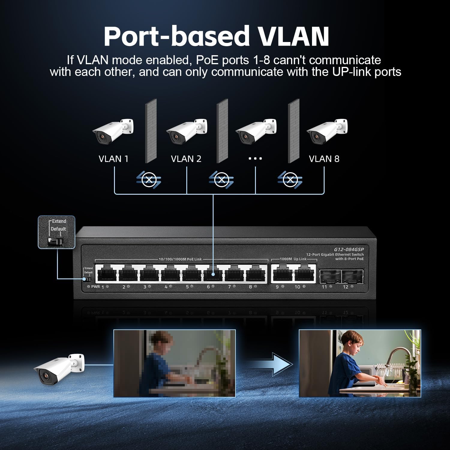
Image: Diagram showing how port-based VLAN isolates PoE ports 1-8, allowing them to communicate only with uplink ports.
Note: It is recommended to change the DIP switch position only when the switch is powered off to avoid potential network disruptions.
Maintenance
- Cleaning: Use a soft, dry cloth to clean the exterior of the switch. Do not use liquid or aerosol cleaners.
- Ventilation: Ensure that the ventilation openings are not blocked. Although fanless, proper airflow helps maintain optimal operating temperature.
- Power Cycle: If the switch experiences unusual behavior, try power cycling it by disconnecting the power cable for a few seconds and then reconnecting it.
- Cable Management: Keep network cables organized and free from kinks or excessive bends to ensure reliable data transmission.
Troubleshooting
Common Issues and Solutions
| Problem | Possible Cause | Solution |
|---|---|---|
| No power (PWR LED off) | Power cable not connected or power outlet is off. | Ensure the power cable is securely connected to the switch and the power outlet. Check the power outlet with another device. |
| Device not receiving power from PoE port |
|
|
| No network connection (Link/Act LED off) |
|
|
| Network performance issues |
|
|
Specifications
| Model | 12x1G PoE |
| Ports | 8 x 10/100/1000 Mbps PoE+ Ports, 2 x 10/100/1000 Mbps RJ45 Uplink Ports, 2 x 1000 Mbps SFP Uplink Ports |
| PoE Standard | IEEE 802.3af/at |
| Total PoE Power Budget | 135W (Internal Power Supply) |
| Max Power Per PoE Port | 30W |
| PoE Output Voltage | 44-57V |
| Data Transfer Rate | 22 Gbps (Backplane Bandwidth) |
| Packet Forwarding Rate | 14.88 Mpps |
| Jumbo Frame Support | 9216 bytes |
| MAC Address Table Size | 2K |
| Switching Architecture | Store-and-Forward |
| Flow Control | IEEE 802.3x |
| Features | Unmanaged, Plug and Play, Port-based VLAN (DIP switch), Auto-Negotiation, Auto-MDI/MDI-X, Auto-Correction, No-Blocking Wire Speed, Fanless Design, 4KV Lightning Protection, Wall Mountable |
| Casing | Metal |
| Operating Temperature | Up to 40°C (104°F) |
| Compatible Devices | IP Cameras, Wireless Access Points, IP Phones, Printers, Computers, Laptops, NVRs |

Image: Visual representation of the switch's performance, highlighting 24Gbps backplane bandwidth, 135W PoE budget, 8 Gigabit PoE ports, 2 Gigabit RJ45 uplink ports, 2 Gigabit SFP uplink ports, a 14.88 Mpps packet forwarding rate, and a 2K MAC address table.
Safety Information
- Do not expose the device to water or excessive humidity.
- Do not open the casing of the switch. There are no user-serviceable parts inside.
- Ensure proper ventilation to prevent overheating.
- Use only the provided power adapter.
- Protect the power cable from being walked on or pinched.
- Disconnect power during lightning storms or when unused for long periods.
Warranty and Support
Binardat provides lifetime technical support for this product. For warranty information or technical assistance, please contact your vendor or visit the official Binardat website.
Note: Specific warranty terms may vary by region and retailer. Please refer to your purchase documentation for details.