DWDBHXDX TOQ7e-125/2 100A
DWDBHXDX Dual Power Automatic Transfer Switch User Manual
Model: TOQ7e-125/2 (100A Variant)
1. Introduction
This user manual provides comprehensive instructions for the installation, operation, and maintenance of the DWDBHXDX Dual Power Automatic Transfer Switch, Model TOQ7e-125/2. This device is designed to automatically switch between two power sources (e.g., utility power and generator) to ensure uninterrupted power supply to critical loads. This specific manual covers the 100A variant, suitable for 110V-120V AC systems.
2. Safety Information
WARNING: Installation and maintenance should only be performed by qualified electricians. Failure to follow these instructions may result in electric shock, fire, or serious injury.
- Always disconnect all power sources before installing or servicing the switch.
- Verify voltage and current ratings match your application.
- Ensure proper grounding to prevent electrical hazards.
- Do not operate the switch if it is damaged or appears to be malfunctioning.
- The product works with L+N 110-120V 50-60Hz systems.
3. Product Overview
The DWDBHXDX Automatic Transfer Switch (ATS) is designed for reliable and safe power transfer. It features a compact design and clear indicators for power source status.

Figure 3.1: Front View of the ATS Unit
This image displays the main components of the automatic transfer switch. On the left, there are clearly labeled input terminals for "City Power" (Source A) and "Generator" (Source B), each with R (Live) and N (Neutral) connections. The central part features a blue rotary switch for manual operation and a control panel with "Manual" and "Auto" settings, along with indicator lights for Source A and Source B. On the right, there are output terminals labeled "AR AN NC C NO" and "BR BN NC C NO" for control signals. The device also indicates "CE WiFi App: eWeLink" and key specifications like "Rated working current 125A" and "Rated working voltage 110V".
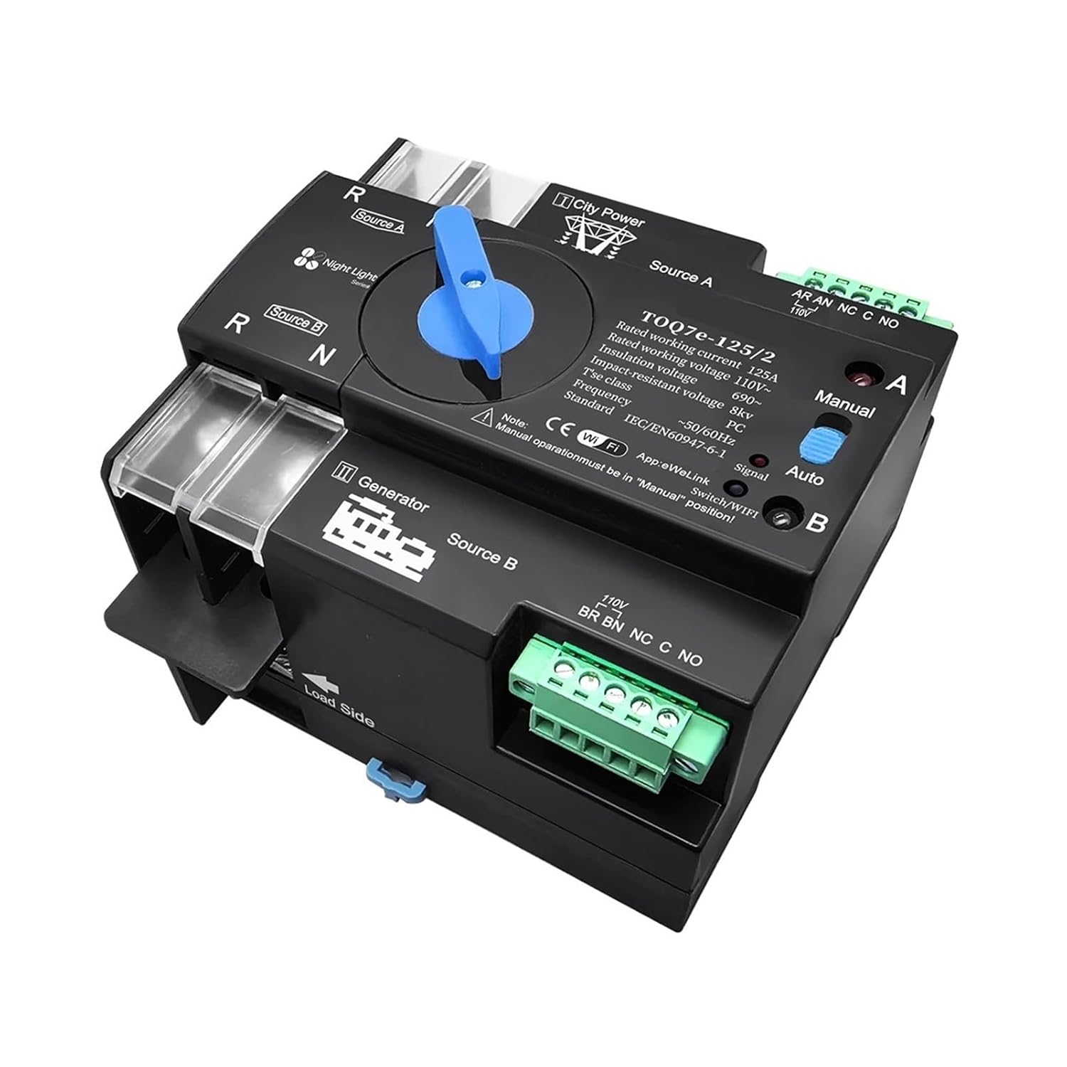
Figure 3.2: Angled View of the ATS Unit
This angled view provides a better perspective of the ATS unit, showing the depth and arrangement of its components. It clearly shows the robust terminal blocks for power connections on the left, the blue manual selector switch, and the control panel on the top right. The green terminal block for control signals is also visible on the right side. The "Load Side" arrow indicates the direction of power flow to the connected loads.

Figure 3.3: Side View of the ATS Unit
This side view focuses on the "Load Side" output terminals, indicating where the power is delivered to the electrical loads. The robust screw terminals are visible, designed for secure wire connections. This perspective also highlights the compact form factor of the device and potential mounting points.
3.1 Key Features
- Automatic and Manual Transfer Modes
- Dual Power Source Input (City Power and Generator)
- Rated for 110V-120V AC, 50/60Hz Systems
- High Impulse Withstand Voltage (8KV)
- Long Electrical and Mechanical Life
- Compact and Durable Design
- Integrated WiFi for Smart Control (eWeLink App compatible)
4. Setup and Installation
Before beginning installation, ensure all power is disconnected from both utility and generator sources.
4.1 Wiring Diagram (Conceptual)
Connect the main utility power (Source A) to the designated "City Power" terminals (R and N). Connect the generator power (Source B) to the "Generator" terminals (R and N). The load side terminals should be connected to your critical loads. Ensure all connections are secure and properly insulated.
- Mounting: Securely mount the ATS unit in a suitable electrical enclosure, ensuring adequate ventilation and clearance for wiring.
- Source A Connection: Connect the Live (L) and Neutral (N) wires from your primary power source (e.g., utility grid) to the "Source A" terminals.
- Source B Connection: Connect the Live (L) and Neutral (N) wires from your secondary power source (e.g., generator) to the "Source B" terminals.
- Load Connection: Connect the Live (L) and Neutral (N) wires leading to your electrical loads to the "Load Side" terminals.
- Control Wiring (Optional): If using external control signals or monitoring, connect to the "AR AN NC C NO" and "BR BN NC C NO" terminals as per your system requirements.
- Grounding: Ensure the unit and associated wiring are properly grounded according to local electrical codes.
- Power On: Once all connections are verified, restore power to Source A and Source B.
5. Operating Instructions
The ATS unit can operate in two modes: Automatic and Manual.
5.1 Automatic Mode
In Automatic mode, the switch will automatically detect the availability of power sources and transfer the load accordingly.
- Set the selector switch on the unit to the "Auto" position.
- When Source A (City Power) is present, the unit will connect the load to Source A.
- If Source A fails, the unit will automatically transfer the load to Source B (Generator) if Source B is available.
- When Source A is restored, the unit will automatically transfer the load back to Source A after a brief delay.
5.2 Manual Mode
Manual mode allows you to manually select the power source.
- Set the selector switch on the unit to the "Manual" position.
- Rotate the blue rotary switch to select either Source A or Source B.
- Note: Manual operation must be in the "Manual" position.
5.3 WiFi Connectivity (eWeLink App)
The ATS unit supports WiFi connectivity for remote monitoring and control via the eWeLink app. Refer to the eWeLink app documentation for pairing and usage instructions. Ensure your WiFi network is 2.4GHz compatible.
6. Maintenance
The DWDBHXDX ATS is designed for minimal maintenance. However, periodic checks are recommended to ensure optimal performance and safety.
- Visual Inspection: Periodically inspect the unit for any signs of physical damage, loose connections, or overheating.
- Terminal Tightness: Ensure all wiring terminals remain tight. Loose connections can lead to overheating and potential hazards.
- Cleaning: Keep the unit clean and free from dust and debris. Use a dry, soft cloth for cleaning. Do not use liquid cleaners.
- Functional Test: Periodically test the automatic transfer function by simulating a power outage from Source A (if safe to do so) to ensure the unit transfers to Source B correctly.
7. Troubleshooting
If you encounter issues with your ATS unit, refer to the following common problems and solutions.
| Problem | Possible Cause | Solution |
|---|---|---|
| Unit does not power on. | No power to input terminals; incorrect wiring. | Check power supply to Source A and Source B. Verify all wiring connections are correct and secure. |
| Automatic transfer not occurring. | Selector switch in "Manual" mode; power source not detected; fault in unit. | Ensure selector switch is in "Auto" position. Verify both power sources are active and within specified voltage range. If problem persists, contact support. |
| Load not receiving power. | No active power source; load wiring issue; internal fault. | Check if Source A or Source B is active. Verify load side wiring. If unit is powered but no output, contact support. |
| WiFi connection issues. | Incorrect WiFi password; 5GHz network; distance from router. | Ensure correct 2.4GHz WiFi network is selected. Move unit closer to router. Re-pair with eWeLink app. |
8. Specifications
| Parameter | Value |
|---|---|
| Model Number | TOQ7e-125/2 |
| Rated Working Current | 100A (This variant, also available in 63A, 125A) |
| Rated Supply Voltage (Us) | AC (L+N) 110V-120V, 50Hz-60Hz |
| Working Condition Voltage | 85% Us ~ 110% Us |
| Rated Impulse Withstand Voltage (KV) | 8KV |
| Electrical Life | 2000 times |
| Mechanical Life | 5000 times |
| Standard | IEC/EN60947-6-1 |
| TSC Class | PC |
| Package Dimensions | 0.39 x 0.39 x 0.39 inches |
| Manufacturer | DWDBHXDX |
9. Warranty and Support
For warranty information and technical support, please contact your retailer or the manufacturer, DWDBHXDX. Keep your purchase receipt as proof of purchase.
For further assistance, please refer to the contact information provided with your purchase or visit the official DWDBHXDX website.
Ask a question about this manual
Ask about setup, troubleshooting, compatibility, parts, safety, or missing instructions. Manuals+ will review the question and use this page’s manual context to help answer it.