1. Introduction
This manual provides essential information for the safe and efficient installation, operation, and maintenance of the NFlixin 9600D Mini Variable Frequency Drive (VFD). Please read this manual thoroughly before using the product to ensure proper functionality and to prevent potential hazards. Keep this manual for future reference.
2. Safety Information
WARNING: Electrical shock hazard. Only qualified personnel should perform installation, wiring, and maintenance procedures.
- Ensure the power supply is disconnected before performing any wiring or maintenance.
- Verify proper grounding of the VFD and the motor.
- Do not touch internal components immediately after power-off, as residual voltage may be present. Wait for the charge indicator to extinguish.
- Install the VFD in a clean, dry, and well-ventilated environment, away from direct sunlight, corrosive gases, and flammable materials.
- Use appropriate personal protective equipment (PPE) during installation and maintenance.
3. Product Overview
The NFlixin 9600D Mini VFD is designed for precise motor speed control, offering advanced features in a compact form factor. It supports 3-phase input/output compatibility for industrial motors and includes advanced vector control technology for accurate torque and speed regulation.
Key Features:
- 3-phase input/output compatibility for industrial motors (supports 110V-480V AC wide voltage range).
- Advanced vector control technology for precise torque/speed regulation (±0.5% speed accuracy).
- Compact design with IP55-rated dust/water-resistant enclosure for harsh workshop conditions.
- Integrated PID controller, RS485 communication, and multiple I/O ports for automation system integration.
- Energy-saving mode automatically adjusts output to match load demands (30%-60% power consumption reduction).
Component Identification:
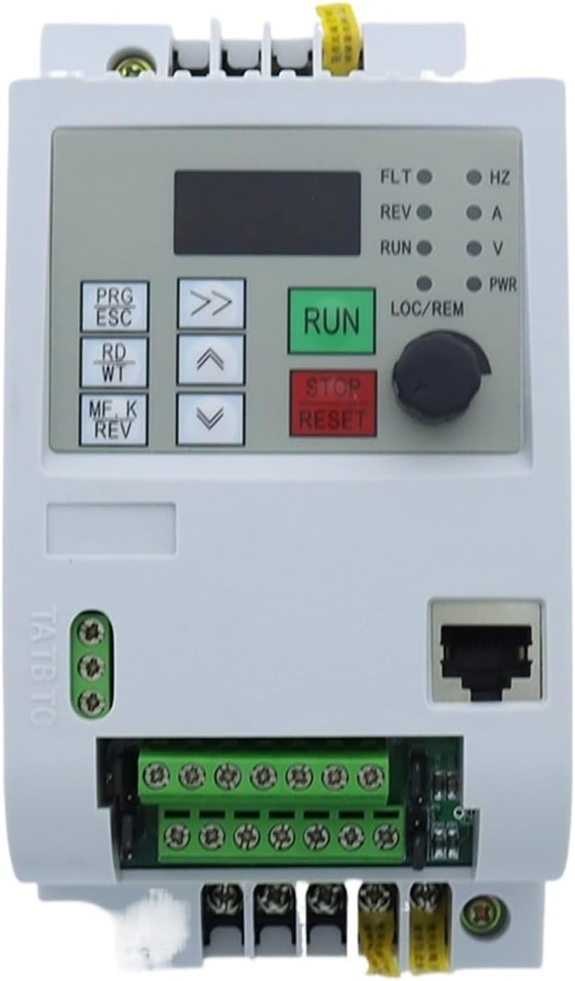
Figure 3.1: Front View. This image displays the front of the NFlixin 9600D VFD, featuring the digital display, control buttons (PRG/ESC, RD/WT, MF.K/REV, RUN, STOP/RESET), navigation arrows, and a rotary knob for frequency adjustment. Status indicator lights for FLT, REV, RUN, LOC/REM, HZ, A, V, and PWR are also visible.

Figure 3.2: Angled Front View. An angled view of the VFD, highlighting the control panel and the accessible terminal blocks at the bottom for input/output connections. The ventilation grilles on the side are also visible.

Figure 3.3: Side View. This image shows the side profile of the VFD, emphasizing the extensive heat sink fins designed for efficient thermal dissipation.

Figure 3.4: Angled Rear View. An angled view from the rear, displaying the various terminal blocks for control wiring, the Ethernet port, and the integrated cooling fan at the bottom.

Figure 3.5: Bottom View. This image provides a view of the bottom section of the VFD, clearly showing the main power input/output terminals (U, V, W, P, B) and the cooling fan.

Figure 3.6: Rear Heat Sink View. A direct rear view of the VFD, showcasing the large aluminum heat sink structure and the bottom-mounted cooling fan.
4. Setup and Installation
4.1 Mounting
- Mount the VFD vertically on a stable, non-flammable surface.
- Ensure adequate clearance (at least 10 cm) around the VFD for proper ventilation and heat dissipation.
- Avoid mounting in areas subject to excessive vibration, dust, or moisture.
4.2 Wiring
Refer to the wiring diagram provided with your specific unit for detailed connections. Below are general guidelines:
- Power Input (R, S, T or L1, L2, L3): Connect the 220V AC 3-phase power supply to the designated input terminals. Ensure correct phase sequence.
- Motor Output (U, V, W): Connect the motor's three-phase windings to the VFD's output terminals U, V, W.
- Grounding (PE): Connect the VFD's ground terminal to a reliable earth ground.
- Control Terminals: Connect external control signals (e.g., start/stop, speed reference, fault reset) to the appropriate control terminals (X1, X2, X3, X4, AI1, AI2, +10V, GND, COM, 485+, 485-). Consult the detailed wiring diagram for specific functions.
Always double-check all wiring connections before applying power.
5. Operating Instructions
5.1 Initial Power-Up
- After verifying all wiring, apply power to the VFD.
- The display should illuminate, showing the default frequency or a status code.
- Check for any fault indicators (FLT LED). If a fault occurs, refer to the Troubleshooting section.
5.2 Basic Operation
- Start/Stop: Press the RUN button to start the motor and the STOP/RESET button to stop it.
- Frequency Adjustment: Use the rotary knob or the up/down arrow buttons to adjust the output frequency, which controls the motor speed.
- Parameter Setting: Use the PRG/ESC button to enter the parameter setting mode. Navigate through parameters using the arrow buttons and modify values using the rotary knob or arrow buttons. Press RD/WT to save changes.
- Forward/Reverse: The MF.K/REV button can be used to toggle the motor's rotation direction if configured.
5.3 Advanced Functions
The NFlixin 9600D VFD supports various advanced functions such as PID control, multi-speed operation, and communication via RS485. Refer to the detailed programming manual (if provided separately) for configuration of these features.
6. Maintenance
Regular maintenance ensures the longevity and reliable operation of your VFD.
- Cleaning: Periodically clean the VFD's exterior and ventilation grilles to prevent dust accumulation, which can impede cooling. Use a soft, dry cloth. Do not use liquid cleaners.
- Inspection: Regularly inspect wiring connections for tightness and signs of wear or damage. Check for any unusual noises or odors during operation.
- Cooling Fan: Ensure the cooling fan operates freely and is not obstructed. Replace if it becomes noisy or stops functioning.
- Environmental Conditions: Verify that the operating environment remains within the specified temperature and humidity ranges.
7. Troubleshooting
This section provides solutions for common issues. For problems not listed here, contact technical support.
| Problem | Possible Cause | Solution |
|---|---|---|
| VFD does not power on | No input power; Blown fuse; Incorrect wiring | Check power supply; Inspect fuses; Verify wiring connections. |
| Motor does not run | VFD in stop mode; Fault condition; Incorrect motor parameters | Press RUN; Check fault codes and clear; Verify motor parameters (e.g., frequency, voltage). |
| Motor runs in wrong direction | Incorrect phase sequence; Reverse command active | Swap any two motor output phases (U, V, W); Check reverse parameter setting or MF.K/REV button. |
| Overcurrent fault (OC) | Motor overload; Short circuit; Rapid acceleration/deceleration | Reduce load; Check motor and wiring for shorts; Adjust acceleration/deceleration times. |
| Overvoltage fault (OV) | High input voltage; Rapid deceleration with high inertia load | Check input voltage; Increase deceleration time; Consider adding a braking resistor. |
8. Specifications
| Parameter | 0.75KW Model | 1.5KW Model | 2.2KW Model |
|---|---|---|---|
| Input Voltage | 220V (+/-15%) | 220V (+/-15%) | 220V (+/-15%) |
| Output Voltage | 220VAC (3-phase) | 220VAC (3-phase) | 220VAC (3-phase) |
| Input Frequency | 50/60Hz | 50/60Hz | 50/60Hz |
| Output Frequency | 0~400Hz | 0~400Hz | 0~400Hz |
| Rated Current | 4A | 7A | 10A |
| Control Method | V/F Control | ||
| Protection Level | Universal (IP55-rated enclosure) | ||
| Dimensions (L x W x H) | Approximately 155mm x 82mm x 135mm | ||
| Weight | Approximately 1 KG (2.2 lbs) | ||
| Certification | CE | ||
9. Warranty and Support
This product is manufactured by Generic. For warranty information, technical support, or service inquiries, please refer to the documentation provided at the time of purchase or contact your vendor. Keep your purchase receipt as proof of purchase.


