Generic ZUKED-320-0.75KW VFD Variable Frequency Drive User Manual
Model: ZUKED-320-0.75KW
1. Introduction
This manual provides essential information for the safe and efficient installation, operation, and maintenance of the Generic ZUKED-320-0.75KW Variable Frequency Drive (VFD). This device is designed to control the speed of 3-phase AC motors by varying the frequency and voltage of the power supplied to the motor. Please read this manual thoroughly before installation and operation to ensure proper usage and to prevent damage to the equipment or injury to personnel.
2. Safety Information
WARNING: Improper installation or operation can lead to serious injury or death. Only qualified personnel should install, operate, or maintain this equipment. Always disconnect power before performing any work on the VFD.
- Electrical Shock Hazard: This VFD operates at high voltages. Do not touch electrical components when power is applied. Wait at least 10 minutes after disconnecting power for capacitors to discharge before servicing.
- Grounding: Ensure the VFD is properly grounded according to local and national electrical codes.
- Environment: Install the VFD in a clean, dry, and well-ventilated area, away from direct sunlight, corrosive gases, flammable materials, and excessive vibration.
- Mounting: Mount the inverter on a non-combustible surface.
- Overcurrent Protection: Ensure appropriate overcurrent protection devices are installed in the input power circuit.
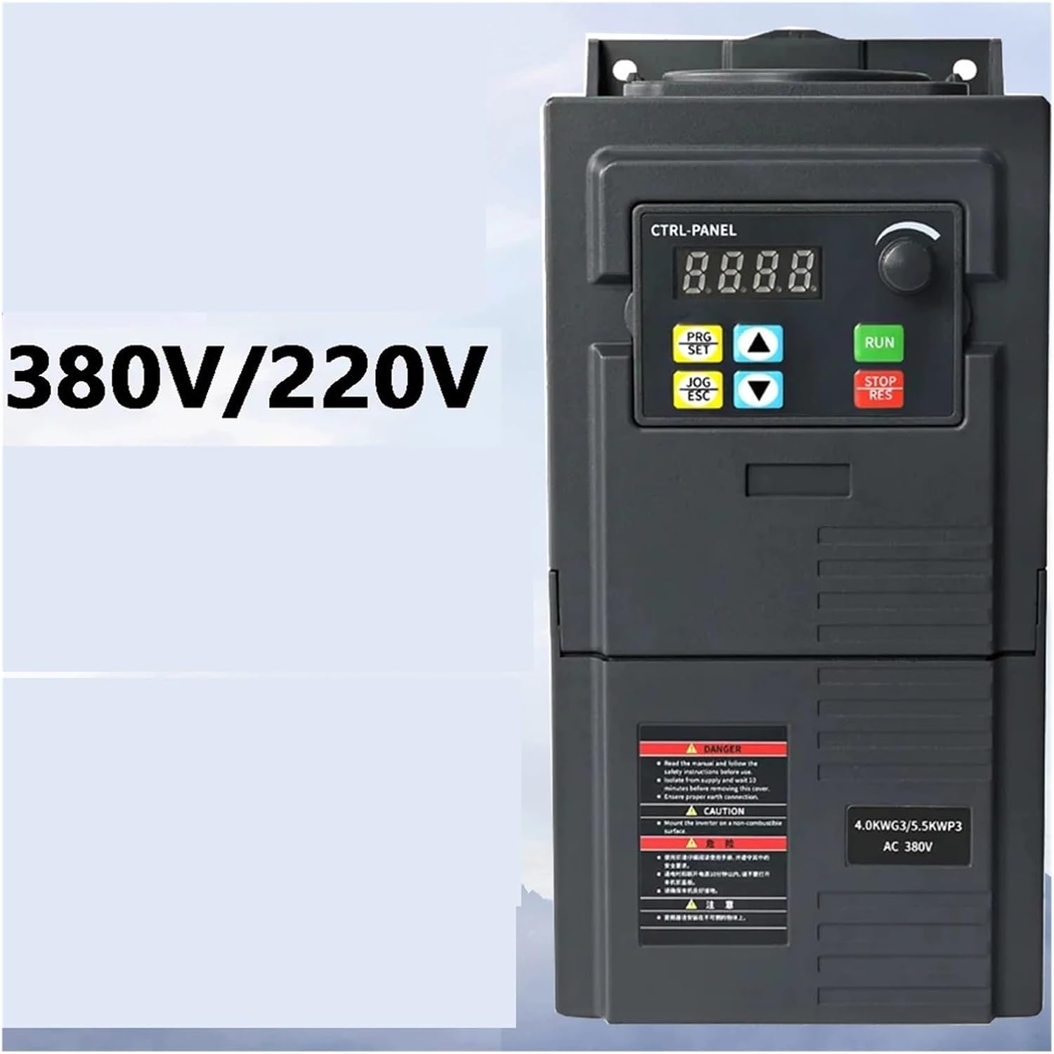
Figure 1: Front view of the VFD, showing the control panel and important safety labels. Note the 'DANGER' and 'CAUTION' warnings regarding electrical hazards and proper installation.
3. Product Overview
The ZUKED-320-0.75KW VFD is a robust variable frequency drive designed for precise motor speed control in industrial applications. It features advanced vector control technology for accurate torque and speed regulation.
Key Features:
- 3-phase input/output compatibility (380V).
- Advanced vector control technology for precise torque/speed regulation (±0.5% speed accuracy).
- Dual analog input.
- Comprehensive protection: Overcurrent, overvoltage, overload, phase loss, short circuit.
- Simple PLC function for basic automation tasks.
- Built-in PID controller for process control.
- Output voltage regulation (AVR function).
- Built-in EMC filter to reduce electromagnetic interference.
- Energy-saving mode: Automatically adjusts output to match load demands.
4. Setup and Installation
4.1. Unpacking and Inspection
Upon receiving the VFD, carefully inspect the packaging for any signs of damage. Open the package and verify that all components are present and undamaged. If any damage is found or parts are missing, contact your supplier immediately.
4.2. Mounting
The VFD should be mounted vertically on a flat, non-combustible surface to ensure proper heat dissipation. Allow sufficient clearance around the unit for ventilation (at least 10 cm on all sides). Use appropriate screws and mounting hardware for secure installation.

Figure 2: Side view of the VFD, highlighting the ventilation grilles and potential mounting points on the rear panel. Proper airflow is crucial for cooling.

Figure 3: Bottom view of the VFD, illustrating the internal capacitors and the design of the mounting brackets for secure installation.
4.3. Wiring
All wiring must be performed by a qualified electrician. Ensure power is disconnected before making any connections.
4.3.1. Power Wiring
- Input Power (R, S, T): Connect the 3-phase 380V AC power supply to the R, S, T terminals.
- Motor Output (U, V, W): Connect the 3-phase motor to the U, V, W terminals.
- Grounding (PE): Connect the ground wire to the PE terminal. This is critical for safety.
4.3.2. Control Wiring
The VFD supports various control inputs for start/stop, speed reference, and fault indications. Refer to the detailed wiring diagram provided with the product for specific terminal assignments for dual analog input, RS485 communication, and other I/O ports.
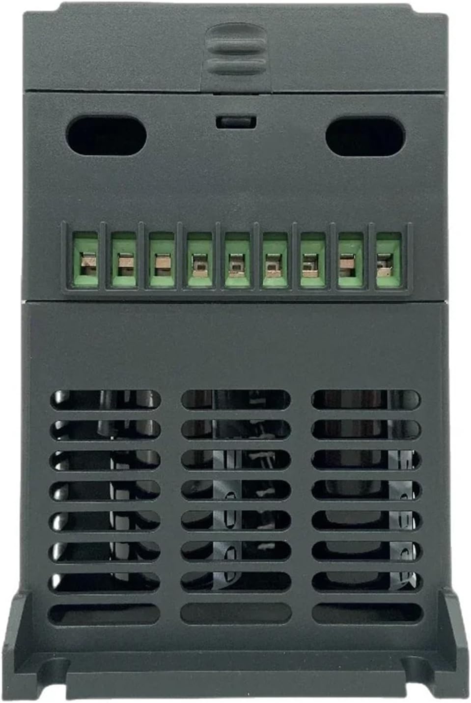
Figure 4: Rear view of the VFD, displaying the terminal block where power input, motor output, and control signals are connected. Ensure all connections are secure and correctly polarized.

Figure 5: Angled view of the VFD, illustrating the main unit and a separate, possibly removable, terminal block for control wiring, emphasizing modularity and ease of connection.
5. Operating Instructions
5.1. Control Panel Overview
The VFD features a digital display and control buttons for parameter setting and operation. The display shows operational status, frequency, current, and other parameters. Buttons include PRG/SET, JOG/ESC, UP/DOWN arrows, RUN, and STOP/RES.
5.2. Basic Operation
- Power On: Apply 3-phase 380V AC power to the VFD. The display will light up.
- Set Frequency: Use the UP/DOWN arrow buttons or the rotary encoder (if present) to set the desired output frequency.
- Start Motor: Press the RUN button to start the motor.
- Stop Motor: Press the STOP/RES button to stop the motor.
5.3. Parameter Settings
The VFD has numerous parameters that can be adjusted to optimize performance for specific applications. These include acceleration/deceleration times, motor parameters, control modes (V/F, vector control), and PID settings.
- Enter Programming Mode: Press the PRG/SET button.
- Navigate Parameters: Use the UP/DOWN arrows to scroll through parameter groups and individual parameters.
- Edit Parameter: Press PRG/SET again to enter edit mode for a selected parameter. Use UP/DOWN to change the value.
- Save and Exit: Press PRG/SET to save the new value, then JOG/ESC to exit programming mode.
Refer to the detailed parameter list in the full product manual for specific parameter codes and their functions.
6. Maintenance
Regular maintenance ensures the longevity and reliable operation of the VFD. Always disconnect power before performing any maintenance.
- Cleaning: Periodically clean the VFD's exterior and ventilation grilles to prevent dust accumulation, which can hinder cooling. Use a soft, dry cloth. Do not use liquid cleaners.
- Inspection: Regularly inspect wiring connections for tightness and signs of wear or damage. Check for any unusual noises or odors during operation.
- Fan Check: Ensure the cooling fan operates freely and is not obstructed.
- Environmental Check: Verify that the operating environment remains within specified temperature and humidity ranges.
7. Troubleshooting
This section provides solutions for common issues. For complex problems, contact technical support.
| Problem | Possible Cause | Solution |
|---|---|---|
| VFD does not power on | No input power; Blown fuse; Loose wiring | Check power supply; Replace fuse; Verify wiring connections. |
| Motor does not run | Incorrect parameters; Motor wiring error; External fault signal | Check motor parameters (voltage, current, frequency); Verify motor wiring (U, V, W); Check control input signals. |
| Overcurrent fault (OC) | Motor overload; Short circuit in motor or wiring; Rapid acceleration/deceleration | Reduce motor load; Check motor and wiring for shorts; Increase acceleration/deceleration times. |
| Overvoltage fault (OV) | High input voltage; Rapid deceleration with high inertia load | Check input voltage; Increase deceleration time; Consider adding a braking resistor if applicable. |
| Overload fault (OL) | Motor or VFD overloaded | Reduce motor load; Check motor current settings; Ensure VFD capacity matches motor requirements. |
8. Specifications
| Feature | Description |
|---|---|
| Model | ZUKED-320-0.75KW |
| Input Voltage | 3-phase 380V |
| Output Voltage | 3-phase 380V |
| Output Power | 0.75KW |
| Output Current | 3.8A (for 0.75KW model) |
| Output Frequency | 0-400Hz |
| Control Method | Vector Control, V/F Control |
| Protection | Overcurrent, Overvoltage, Overload, Phase Loss, Short Circuit |
| Built-in Features | PID Controller, EMC Filter, Simple PLC Function, AVR Function |
| Dimensions (Approx.) | 0.39 x 0.39 x 0.39 inches (Package Dimensions) |
| Item Weight | 3.53 ounces (100 Grams) |
9. Warranty and Support
For warranty information, technical support, or service inquiries, please contact the seller or manufacturer directly. Keep your purchase receipt and product model number handy for faster assistance.


