1. Product Overview
This manual provides essential instructions for the safe and efficient operation, installation, and maintenance of the NFlixin 9600D Variable Frequency Drive (VFD). The NFlixin 9600D is designed for precise motor speed control in various industrial applications. This document specifically covers the 220V 1.5KW 7A model.
Key features include advanced vector control technology for precise torque and speed regulation, an integrated PID controller, RS485 communication, and multiple I/O ports for automation system integration. The unit also incorporates an energy-saving mode to optimize power consumption.
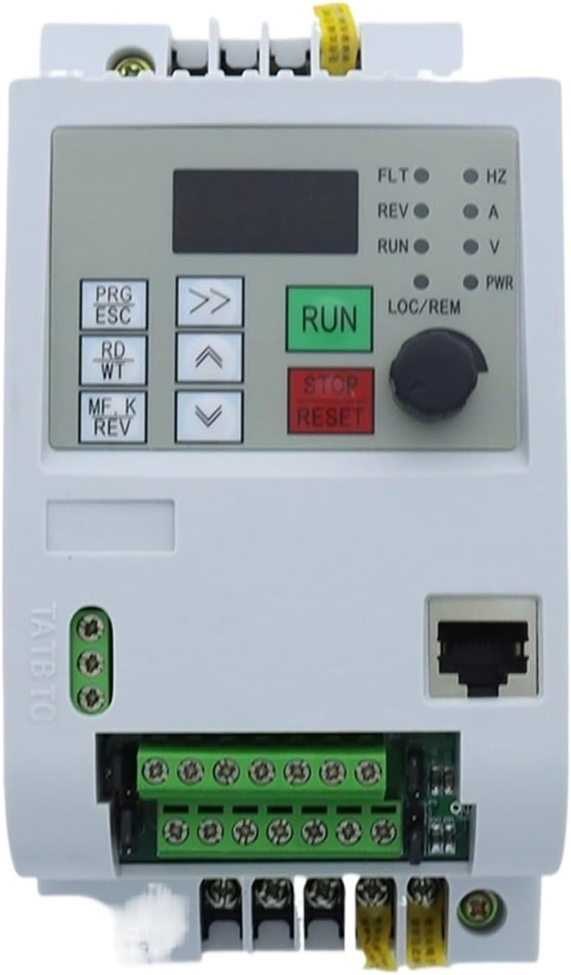
Figure 1: Front view of the NFlixin 9600D VFD, showing the control panel and terminal blocks.
2. Setup and Installation
2.1 Unpacking and Inspection
Upon receiving the VFD, carefully unpack it and inspect for any signs of damage during transit. Verify that all components are present according to the packing list. If any damage or missing parts are found, contact your supplier immediately.
2.2 Mounting
Mount the VFD in a vertical position on a flat, non-flammable surface. Ensure adequate ventilation space around the unit (at least 10 cm on all sides) to allow for proper heat dissipation. Avoid mounting in direct sunlight, high humidity, excessive dust, or corrosive environments. The VFD features an IP55-rated enclosure for dust and water resistance, but optimal conditions prolong its lifespan.

Figure 2: Side view of the NFlixin 9600D VFD, highlighting the heat sink fins for cooling.
2.3 Wiring
All wiring must be performed by qualified personnel in accordance with local and national electrical codes. Ensure power is disconnected before making any connections.
2.3.1 Power Input (R, S, T)
Connect the 220V single-phase AC power supply to the R and T terminals. The VFD will convert this to a 3-phase output for the motor. Ensure the input voltage matches the VFD's rating (220V +/-15%).
2.3.2 Motor Output (U, V, W)
Connect the three-phase motor leads to the U, V, and W terminals. Ensure correct phase sequence for desired motor rotation. If the motor rotates in the wrong direction, swap any two of the U, V, W connections.
2.3.3 Grounding (PE)
Connect the ground terminal (PE) of the VFD to a reliable earth ground. This is crucial for safety and to minimize electromagnetic interference.
2.3.4 Control Terminals
The VFD provides various control terminals for external control signals. Refer to the diagram below for terminal identification:
- X1, X2, X3, X4: Multi-function digital input terminals (e.g., start, stop, jog, multi-speed selection).
- 485+, 485-: RS485 communication interface for external control via Modbus protocol.
- AI1, AI2: Analog input terminals (e.g., 0-10V or 4-20mA for speed reference).
- +10V, GND: 10V power supply and ground for analog input sensors.
- 24V, COM: 24V power supply and common for digital inputs.
- D01: Multi-function digital output terminal.

Figure 3: Top view of the NFlixin 9600D VFD, showing the control terminal block for external connections.

Figure 4: Bottom view of the NFlixin 9600D VFD, illustrating the main power input/output terminals and cooling fan.
3. Operating Instructions
3.1 Control Panel Overview
The VFD features a user-friendly control panel for local operation and parameter setting.

Figure 5: Close-up of the NFlixin 9600D VFD control panel, showing buttons, display, and potentiometer.
- PRG/ESC: Program/Escape button. Used to enter/exit parameter setting mode and return to the previous menu.
- RD/WT: Read/Write button. Used to confirm parameter values or save settings.
- MF.K/REV: Multi-function key / Reverse button. Its function can be configured. Often used for motor direction reversal.
- RUN: Green button to start the motor.
- STOP/RESET: Red button to stop the motor or reset fault conditions.
- Up/Down Arrows: Used to navigate menus and adjust parameter values.
- Right Arrow (Shift): Used to shift cursor position during parameter editing.
- Potentiometer (LOC/REM): Used for local speed adjustment. The LOC/REM switch typically toggles between local (potentiometer) and remote (external signal) control modes.
- Display: Shows operating frequency, output current, voltage, and parameter codes.
- Indicator Lights (FLT, REV, RUN, HZ, A, V, PWR): Indicate fault status, reverse rotation, running status, frequency unit, current unit, voltage unit, and power status respectively.
3.2 Basic Operation
- Power On: Apply power to the VFD. The display will light up.
- Select Control Mode: Use the LOC/REM switch or parameter settings to choose between local control (potentiometer) or remote control (external analog/digital signals).
- Set Frequency/Speed:
- Local Control: Adjust the potentiometer on the control panel.
- Remote Control: Provide the desired speed reference via the configured analog input (AI1/AI2) or digital inputs.
- Start Motor: Press the RUN button. The motor will accelerate to the set frequency.
- Stop Motor: Press the STOP/RESET button. The motor will decelerate and stop.
- Reverse Direction: If configured, use the MF.K/REV button or a digital input to change the motor's rotation direction.
3.3 Parameter Setting
The VFD has numerous parameters to configure its operation. Consult the detailed parameter list in the full product manual for specific codes and functions. General steps for parameter setting:
- Press PRG/ESC to enter parameter setting mode.
- Use the Up/Down Arrows to navigate through parameter groups and individual parameters.
- Press RD/WT to view the current value of a parameter.
- Use the Up/Down Arrows to modify the parameter value. Use the Right Arrow to shift the cursor for digit selection.
- Press RD/WT again to save the new value.
- Press PRG/ESC to exit parameter setting mode.
Important Parameters to Configure:
- Motor Parameters: Rated power, rated voltage, rated current, rated frequency, rated speed.
- Acceleration/Deceleration Time: Set appropriate ramp-up and ramp-down times to prevent mechanical stress or overcurrent.
- Maximum Output Frequency: Define the upper limit of the motor speed.
- Control Mode: V/F control, vector control, etc.
4. Maintenance
Regular maintenance ensures the longevity and reliable operation of the NFlixin 9600D VFD. Always disconnect power before performing any maintenance.
- Dust Removal: Periodically clean the VFD's heat sink and cooling fan to prevent dust accumulation, which can impede heat dissipation and lead to overheating. Use compressed air or a soft brush.
- Terminal Inspection: Check all wiring terminals for tightness and corrosion. Loose connections can cause overheating and intermittent operation.
- Cooling Fan: Verify that the cooling fan operates freely and without unusual noise. Replace the fan if it is damaged or excessively noisy.
- Environmental Check: Ensure the operating environment remains within specified temperature and humidity ranges.
5. Troubleshooting
This section provides guidance for common issues. For complex problems or persistent faults, contact technical support.
| Problem | Possible Cause | Solution |
|---|---|---|
| VFD does not power on. | No input power, incorrect wiring, internal fuse blown. | Check input power supply. Verify wiring connections. Inspect internal fuses (if accessible and safe to do so). |
| Motor does not run. | VFD not in RUN state, incorrect frequency setting, motor wiring error, VFD fault. | Press RUN button. Check frequency reference. Verify motor connections (U, V, W). Check VFD display for fault codes and reset if necessary. |
| Motor runs in wrong direction. | Incorrect motor phase sequence. | Swap any two of the motor output wires (U, V, W). |
| VFD displays an error code. | Overcurrent, overvoltage, undervoltage, overheating, motor overload, etc. | Note the error code and consult the full product manual for specific definitions and remedies. Address the underlying cause (e.g., reduce load, check power supply, improve ventilation). Press STOP/RESET to clear the fault after resolving the issue. |
| Abnormal motor noise or vibration. | Incorrect VFD parameters, motor issues, mechanical imbalance. | Verify motor parameters in VFD settings. Check motor bearings and mounting. Consult a motor specialist if necessary. |
6. Specifications
The following table details the technical specifications for the NFlixin 9600D VFD, 220V 1.5KW 7A model.
| Feature | Specification |
|---|---|
| Model Number | 9600D (or 9100-1T / 9600-1T series) |
| Input Voltage | 1-phase 220V (+/-15%) |
| Output Voltage | 3-phase 220VAC |
| Input Frequency | 50/60Hz |
| Output Frequency | 0~400Hz |
| Rated Power | 1.5KW |
| Rated Current | 7A |
| Control Method | V/F Control (Vector Control capable) |
| Dimensions (L x W x H) | 155mm x 82mm x 135mm (approx.) |
| Weight | Approx. 1KG |
| Protection Level | IP55 (enclosure rating) |
| Certification | CE |
7. Warranty and Support
For warranty information, please refer to the terms and conditions provided at the time of purchase or contact your seller directly. Specific warranty periods and coverage details may vary.
For technical support, troubleshooting assistance beyond this manual, or inquiries regarding spare parts, please contact the seller or manufacturer through the provided contact channels. When contacting support, please have your product model number (NFlixin 9600D) and purchase details readily available.