1. Safety Information
Please read and understand all safety instructions before operating the radio. Failure to follow these instructions may result in injury, damage to the radio, or voiding the warranty.
- RF Exposure: Do not operate the radio without a properly installed antenna. Maintain a safe distance from the antenna during transmission.
- Power Supply: Use only the specified 13.8V DC power supply. Ensure correct polarity when connecting the power cable.
- Antenna: Connect a suitable antenna before transmitting. Transmitting without an antenna or with a mismatched antenna can damage the radio.
- Driving Safety: Do not operate the radio in a manner that distracts you from driving. Prioritize road safety.
- Temperature: Avoid exposing the radio to extreme temperatures, direct sunlight for prolonged periods, or excessive moisture.
2. Product Overview
2.1 Key Features
- Dual Band Operation: VHF (136-174MHz) and UHF (400-480MHz) frequency ranges.
- 200 Programmable Memory Channels.
- Supports Single Call, Group Call, Selective Call, and Emergency Call functions.
- CTCSS and DCS tone support for selective signaling.
- VOX (Voice Operated Transmit) function for hands-free operation.
- Lighted Keypad Microphone with built-in speaker.
- Built-in cooling fan for extended operation.
- Durable plastic and metal construction.
2.2 Package Contents
- Anytone AT-778UV II Mobile Radio Unit
- Handheld Microphone with Keypad
- DC Power Cable with Fuse Holder
- Mounting Bracket and Hardware
- User Manual
2.3 Component Identification
Familiarize yourself with the main components of your radio.

Figure 1: Front view of the Anytone AT-778UV II mobile radio with the handheld microphone connected, showing the display and main controls.

Figure 2: Close-up of the 1.77-inch color TFT screen displaying frequency, mode, and voltage information.
- Radio Unit: Features a 1.77-inch color TFT display, power button, P1-P6 programmable function buttons, and a rotary knob for channel/frequency selection and volume.
- Handheld Microphone: Equipped with a full keypad for direct frequency input, PTT (Push-To-Talk) button, A/B band switch, and additional function buttons. It also includes a built-in speaker.
3. Setup and Installation
3.1 Mounting the Radio
Select a secure and well-ventilated location in your vehicle or operating area. Use the provided mounting bracket and hardware to firmly attach the radio. Ensure the location allows for easy access to controls and display, and does not obstruct airbags or driving visibility.
3.2 Power Connection
- Connect the red wire of the DC power cable to the positive (+) terminal of your vehicle's 13.8V DC power source (e.g., battery).
- Connect the black wire to the negative (-) terminal or a suitable ground point.
- Ensure the fuse holder is properly installed in the positive line.
- Plug the DC power connector into the power input port on the rear of the radio unit.
3.3 Antenna Connection
Connect a suitable VHF/UHF dual-band antenna to the antenna connector on the rear of the radio. Ensure the connection is tight and secure. Using an antenna with a high SWR (Standing Wave Ratio) can damage the radio's transmitter.
3.4 Microphone Connection
Plug the handheld microphone's connector into the microphone jack on the front panel of the radio unit. Ensure it clicks into place securely.
4. Operating Instructions
4.1 Powering On/Off
Press and hold the Power Button () on the front panel to turn the radio on or off.
4.2 Volume Adjustment
Rotate the Volume/Channel Knob (rightmost knob) clockwise to increase volume and counter-clockwise to decrease it.
4.3 Frequency and Channel Selection
- VFO Mode (Frequency Mode): Allows direct input of frequencies. Use the handheld microphone's keypad to enter the desired frequency.
- Memory Mode (Channel Mode): Allows selection of pre-programmed channels. Use the Volume/Channel Knob or the microphone's UP/DOWN buttons to scroll through channels.
- Press the VFO/MR button (often assigned to a P-button or accessible via FUNC menu) to switch between VFO and Memory modes.
4.4 Transmitting and Receiving
To transmit, press and hold the PTT (Push-To-Talk) button on the side of the handheld microphone. Speak clearly into the microphone. Release the PTT button to receive.
4.5 VOX Function
The VOX (Voice Operated Transmit) function allows hands-free transmission. When activated, the radio will automatically transmit when it detects your voice.

Figure 3: Illustration of the VOX function in use, showing the handheld microphone and radio display with VOX menu options.
- To activate VOX, navigate to the VOX setting in the radio's menu (refer to Figure 3).
- Adjust the VOX sensitivity level to prevent accidental transmissions or missed voice activation.
4.6 Call Functions
The AT-778UV II supports various call types:
- Single Call: Direct communication with a specific radio.
- Group Call: Communication with a predefined group of radios.
- Selective Call: Similar to single call, but often uses specific ID codes.
- Emergency Call: Transmits an alert signal to all radios within range or a designated emergency channel.
These functions are typically accessed via the radio's menu system or pre-programmed buttons.
4.7 Menu Navigation and Programmable Buttons
The radio features a FUNC button and six programmable buttons (P1-P6) on the front panel. These buttons can be customized for quick access to frequently used functions.
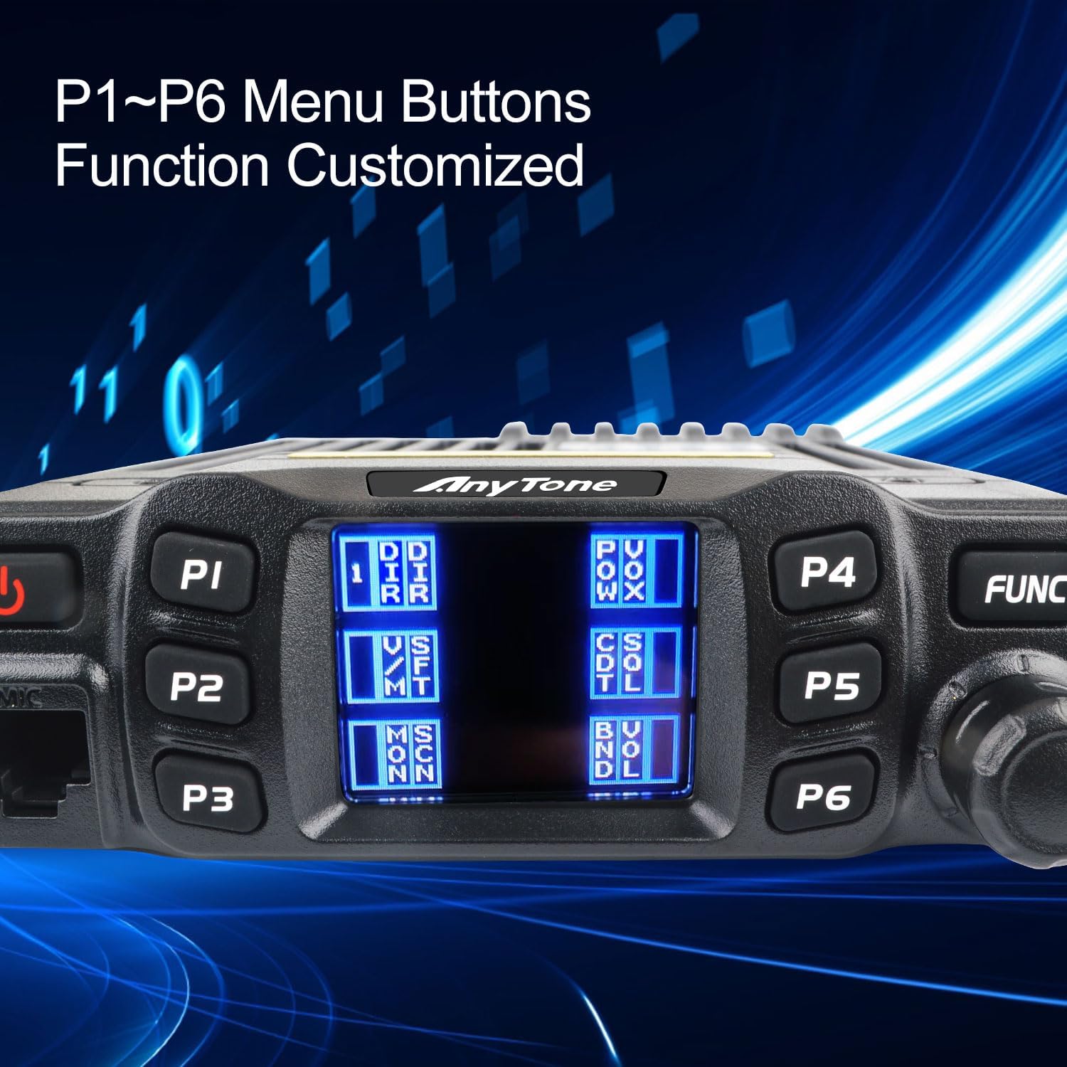
Figure 4: Close-up of the radio's front panel highlighting the P1-P6 programmable menu buttons and their customizable functions.

Figure 5: The radio display showing a menu for 'Relay Pilot Frequency' settings, indicating advanced configuration options.
- Press the FUNC button to enter the main menu.
- Use the Volume/Channel Knob or microphone UP/DOWN buttons to navigate through menu options.
- Press FUNC again or a designated confirmation button to select an option.
- Refer to the full user manual for detailed instructions on customizing P1-P6 buttons and specific menu functions (e.g., Relay Pilot Frequency as shown in Figure 5).
5. Programming
5.1 Memory Channel Programming
The radio allows you to store frequently used frequencies and settings into 200 memory channels.

Figure 6: The radio display showing options for 200 programmable memory channels and settings for 52 groups of CTCSS tones and 1024 groups of DCS codes.
- Enter VFO mode and set the desired frequency.
- Access the memory store function via the menu.
- Select an empty channel number to save the frequency.
- You can also program repeater offsets, CTCSS/DCS tones, and power levels for each channel.
5.2 CTCSS/DCS Tones
CTCSS (Continuous Tone-Coded Squelch System) and DCS (Digital Coded Squelch) tones are used to filter out unwanted signals and allow you to hear only transmissions from radios using the same tone settings. The AT-778UV II supports 52 groups of CTCSS tones and 1024 groups of DCS codes (refer to Figure 6).
- Navigate to the CTCSS/DCS settings in the radio's menu.
- Select the desired tone or code for both transmit (TX) and receive (RX).
6. Maintenance
6.1 Cleaning
Wipe the radio and microphone surfaces with a soft, damp cloth. Do not use harsh chemicals or abrasive cleaners. Ensure no moisture enters the radio's openings.
6.2 General Care
- Regularly check all cable connections for tightness and wear.
- Avoid dropping the radio or subjecting it to strong impacts.
- Ensure adequate ventilation around the radio, especially during prolonged transmission, to prevent overheating.
7. Troubleshooting
If you encounter issues with your radio, refer to the following common problems and solutions:
| Problem | Possible Cause | Solution |
|---|---|---|
| Radio does not power on. | No power connection; Blown fuse; Incorrect wiring. | Check power cable connection; Replace fuse; Verify wiring polarity. |
| Cannot transmit. | Antenna not connected; Incorrect frequency/channel; PTT button malfunction. | Connect antenna; Verify frequency/channel settings; Test PTT button. |
| No reception or poor audio. | Volume too low; Squelch level too high; Incorrect CTCSS/DCS; Antenna issue. | Adjust volume; Lower squelch level; Check CTCSS/DCS settings; Inspect antenna. |
| Display shows error message. | Internal fault; Overheating. | Power cycle the radio; Ensure proper ventilation; If persistent, contact support. |
8. Technical Specifications
| Specification | Value |
|---|---|
| Frequency Range | VHF: 136-174MHz, UHF: 400-480MHz |
| Number of Channels | 200 |
| Channel Spacing | 25K (Wide Band), 20K (Middle Band), 12.5K (Narrow Band) |
| Phase-locked Step | 2.5KHz, 5KHz, 6.25KHz, 8.33KHz, 10KHz, 12.5KHz, 20KHz, 25KHz, 30KHz, 50KHz |
| Operating Voltage | 13.8V DC ± 15% |
| Squelch Type | Carrier/CTCSS/DCS |
| Frequency Stability | ±5ppm |
| Operating Temperature | -20°C to +60°C |
| Dimensions (W*H*D) | 112(W) * 30(H) * 14.2(L) mm |
| Net Weight | Approx. 0.51Kg |
| Transmitter Power Output | Wide Band: 25W/15W/5W; Narrow Band: 25W/15W/5W |
| Audio Power Output | >2W @ 8Ω |
| Water Resistance Level | Not Water Resistant |
9. Warranty and Support
9.1 Warranty Information
This product is provided with No Warranty as per manufacturer specifications.
9.2 Customer Support
For technical assistance, troubleshooting beyond this manual, or inquiries regarding product operation, please contact your authorized dealer or the manufacturer's customer support. Keep your purchase receipt for reference.