1. Introduction
This manual provides essential information for the safe and efficient operation of the RQNKJJCE suswe-310 Variable Frequency Drive (VFD) Inverter, specifically the 310-4KW model. A VFD is an electronic device used to control the speed of an AC motor by varying the frequency and voltage supplied to the motor. This unit is designed for 3-phase 380V input and output applications. Please read this manual thoroughly before installation, operation, or maintenance to ensure proper usage and prevent potential hazards.
2. Safety Information
WARNING: Improper installation or operation can lead to serious injury or death. Only qualified personnel should install, operate, or maintain this equipment.
- Electrical Hazard: This VFD operates with high voltage. Ensure all power is disconnected and verified before performing any wiring or maintenance. Wait at least 5 minutes after power-off for capacitors to discharge.
- Grounding: The VFD must be properly grounded according to local and national electrical codes.
- Installation Environment: Install the VFD in a clean, dry, well-ventilated area, free from corrosive gases, dust, and direct sunlight. Ensure ambient temperature and humidity are within specified limits.
- Motor Compatibility: Ensure the motor connected to the VFD is compatible with its output specifications.
- Emergency Stop: Always ensure an accessible emergency stop mechanism is in place for the controlled system.
3. Product Overview
The RQNKJJCE suswe-310 VFD is a compact and robust unit designed for precise motor speed control. It features a digital display, an intuitive keypad for parameter setting, and clearly labeled terminals for power and control connections.
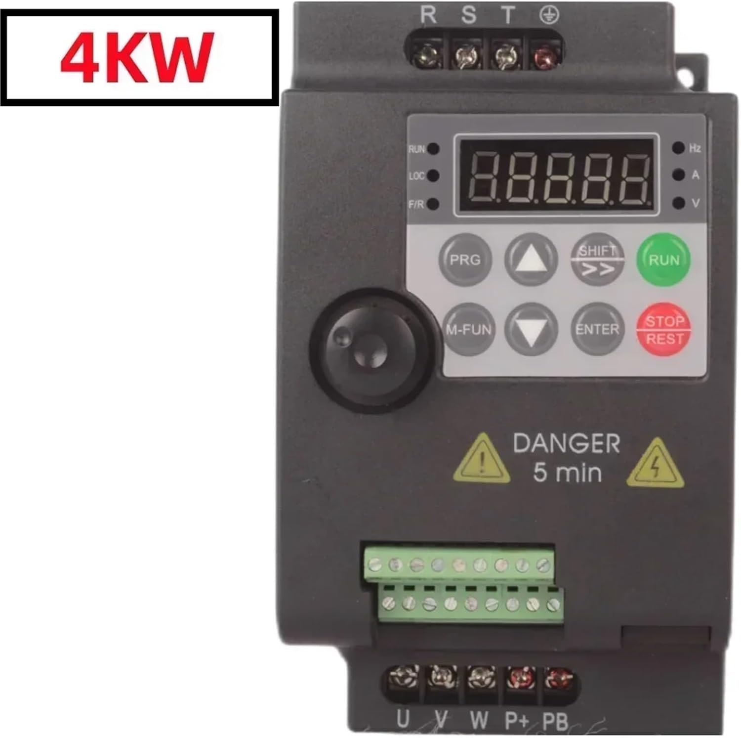
Figure 3.1: Front view of the VFD. This image displays the main control panel, including the digital display, 'RUN' and 'STOP/REST' buttons, and other function keys. The '4KW' label indicates the power rating of this specific model.
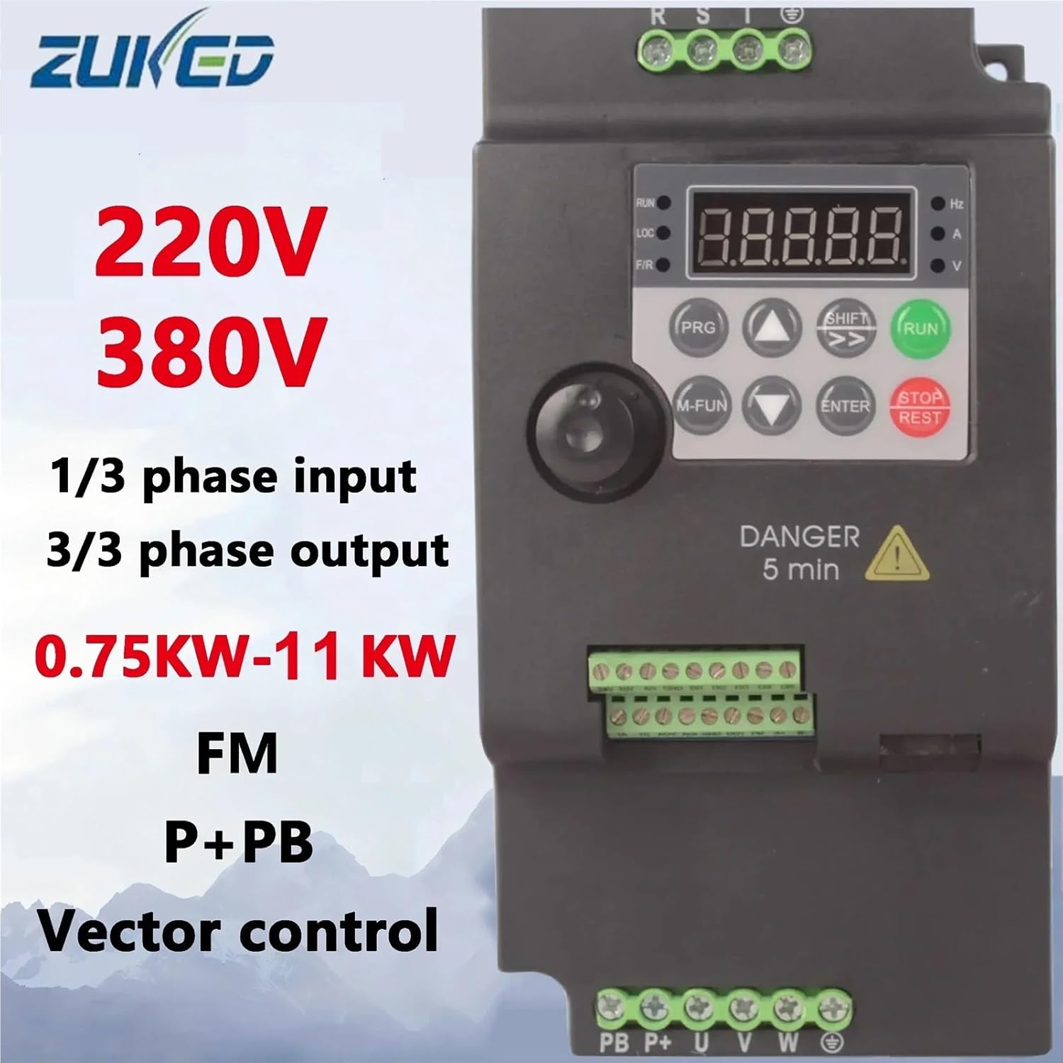
Figure 3.2: General capabilities overview. This image highlights the versatility of the suswe-310 series, indicating support for both 220V and 380V systems, single or three-phase input, three-phase output, and a power range from 0.75KW to 11KW. This specific model is 380V, 3-phase input/output, 4KW.
4. Specifications
| Feature | Specification |
|---|---|
| Brand | RQNKJJCE |
| Model | suswe-310 310-4KW |
| Input Voltage | Three Phase AC 380-440V |
| Output Voltage | Three Phase AC 0-440V |
| Output Power | 4KW |
| Output Frequency | 0-500Hz |
| Control Type | Vector Control |
| Dimensions (L*W*H) | 145mm * 165mm * 205mm |
| Weight | Approximately 1kg |
5. Setup
5.1 Mounting
Mount the VFD vertically on a stable, non-flammable surface. Ensure adequate clearance around the unit for proper ventilation and heat dissipation. Avoid mounting in direct sunlight or near heat sources. The operating environment should be free from excessive vibration, dust, and moisture.
5.2 Wiring
All wiring must be performed by a qualified electrician. Ensure all power is disconnected before beginning any wiring procedures.

Figure 5.1: Terminal blocks for wiring. This image shows the various connection points for input power, motor output, and control signals. Proper identification and connection are crucial for safe operation.
5.2.1 Power Wiring
- Input Power (R, S, T): Connect the 3-phase AC 380-440V power supply to the R, S, and T terminals.
- Motor Output (U, V, W): Connect the 3-phase motor leads to the U, V, and W terminals.
- Grounding (⚧): Connect the protective earth ground to the designated ground terminal. This is critical for safety.
5.2.2 Control Wiring (Optional)
The VFD provides various control terminals for external control signals. Refer to the detailed wiring diagram in the full product manual for specific connections. Common terminals include:
- Analog Input (AI1, 10V, GND): For external speed reference (e.g., potentiometer, 0-10V signal).
- Digital Inputs (DI1-DI5, 24V, GND): For start/stop commands, multi-speed selection, etc.
- Relay Output (TA, TC): Programmable relay output for status indication.
- Analog Output (AO1, FM): For output frequency or current monitoring.
- Communication (A+, B-): For Modbus RTU communication.
6. Operating Instructions
6.1 Keypad Functions
- RUN: Starts the motor.
- STOP/REST: Stops the motor or resets faults.
- PRG: Enters/exits parameter programming mode.
- M-FUN: Multi-function key, often used for quick access to common parameters.
- SHIFT: Shifts cursor during parameter editing or displays different monitoring values.
- ENTER: Confirms parameter settings or enters sub-menus.
- ▲ / ▼ (Up/Down Arrows): Adjusts frequency, navigates menus, or changes parameter values.
6.2 Initial Power-Up
- After completing all wiring and safety checks, apply power to the VFD.
- The digital display should illuminate, typically showing the output frequency or a default parameter.
- Observe for any error codes or unusual behavior. If an error occurs, refer to the Troubleshooting section.
6.3 Basic Operation (Keypad Control)
- Set Frequency: Use the ▲ / ▼ keys to adjust the desired output frequency. The display will show the set frequency.
- Start Motor: Press the RUN button. The motor should start and accelerate to the set frequency.
- Stop Motor: Press the STOP/REST button. The motor will decelerate and stop.
6.4 Parameter Programming
The VFD has numerous parameters to customize its operation. These include acceleration/deceleration times, motor parameters, control modes, and more. Refer to the comprehensive parameter list in the full product manual for detailed descriptions and settings.
- Press the PRG button to enter parameter programming mode.
- Use the ▲ / ▼ keys to navigate through parameter groups and individual parameters.
- Press ENTER to select a parameter or enter a sub-menu.
- Use the ▲ / ▼ keys to change the parameter value. Use SHIFT to move the cursor for digit editing.
- Press ENTER to save the new value.
- Press PRG again to exit programming mode.
7. Maintenance
Regular maintenance ensures the longevity and reliable operation of your VFD.
- Cleaning: Periodically clean the VFD's exterior and cooling fins to prevent dust accumulation, which can hinder heat dissipation. Use a soft, dry cloth. Do not use liquids or solvents.
- Fan Inspection: Check the cooling fan for proper operation and ensure it is free from obstructions. Replace if noisy or not functioning correctly.
- Terminal Connections: Annually inspect all terminal connections for tightness. Loose connections can cause overheating and intermittent operation.
- Environmental Check: Ensure the operating environment remains within specified temperature and humidity ranges.
8. Troubleshooting
This section provides general guidance for common issues. For detailed error codes and advanced troubleshooting, refer to the full product manual.
| Problem | Possible Cause | Solution |
|---|---|---|
| VFD does not power on | No input power; Blown fuse; Loose wiring | Check power supply; Inspect fuses; Verify all power connections. |
| Motor does not run | Incorrect wiring; Motor parameters not set; VFD in fault state; External control issue | Verify motor wiring (U, V, W); Check motor parameters (voltage, current); Clear any fault codes; Check external control signals. |
| Motor runs erratically or vibrates | Incorrect motor parameters; Loose motor connections; Motor overload | Review and adjust motor parameters; Tighten motor connections; Reduce motor load. |
| Overcurrent (OC) fault | Motor overload; Short circuit in motor or wiring; Rapid acceleration/deceleration | Reduce load; Check motor and wiring for shorts; Increase acceleration/deceleration times. |
| Overvoltage (OV) fault | High input voltage; Rapid deceleration with high inertia load | Check input voltage; Increase deceleration time; Consider adding a braking resistor if applicable. |
9. Warranty and Support
For warranty information, technical support, or service inquiries, please contact your vendor or the manufacturer, RQNKJJCE. Keep your purchase receipt and product model information handy for faster assistance. Do not attempt to repair the unit yourself, as this may void the warranty and pose safety risks.