1. Introduction
This manual provides essential information for the safe and efficient installation, operation, and maintenance of your FRPKPNOX RP5D-100A Automatic Transfer Switch (ATS). Please read this manual thoroughly before installation and operation to ensure proper function and prevent potential hazards.
1.1 Safety Information
- WARNING: Electrical shock hazard. Installation and servicing must be performed by qualified personnel only.
- Always disconnect all power sources before working on the ATS or connected equipment.
- Ensure proper grounding to prevent electrical hazards.
- Verify all connections are secure and correctly wired according to local electrical codes and this manual.
- Do not operate the ATS if it appears damaged or malfunctioning.
2. Product Features
The FRPKPNOX RP5D-100A is a PC-rated, 4-pole, 100A Automatic Transfer Switch designed for reliable power source change-over. Key features include:
- Automatic Transfer: Seamlessly switches between two power sources (e.g., utility and generator) when one fails or is restored.
- Manual Override: Allows for manual selection of power sources when automatic operation is not desired.
- Dual Circuit Design: Manages power transfer for two independent circuits.
- High Current Rating: Rated for 100 Amperes, suitable for various industrial and commercial applications.
- Wide Voltage Compatibility: Operates with 220V/380V systems.
- Isolated Type: Provides isolation between power sources.
3. Specifications
| Parameter | Specification |
|---|---|
| Model Number | RP5D-100A |
| Brand | FRPKPNOX |
| Rated Voltage | 220V/380V |
| Rated Current | 100A |
| Poles | 4 |
| Class | PC type |
| Type | Isolated, Basic Type |
4. Installation and Setup
Installation of the RP5D-100A ATS requires adherence to all local and national electrical codes. It is strongly recommended that installation be performed by a certified electrician.
4.1 Pre-Installation Checks
- Ensure the ATS rating matches your system requirements (voltage, current, number of poles).
- Verify that all power sources are disconnected and locked out before beginning installation.
- Inspect the ATS for any physical damage. Do not install if damaged.
4.2 Mounting
Mount the ATS securely in a suitable enclosure or panel, ensuring adequate ventilation and clearance for wiring and operation. Use appropriate fasteners for the mounting brackets.

Image 4.1: Rear view of the ATS, highlighting the mounting brackets for secure installation.
4.3 Wiring Connections
The RP5D-100A ATS features clearly labeled terminals for power source 1 (utility), power source 2 (generator), and load connections. Refer to the wiring diagram provided with your unit for specific connection details. General wiring steps include:
- Connect the main utility power source to the designated input terminals.
- Connect the secondary power source (e.g., generator) to its designated input terminals.
- Connect the load circuits to the output terminals of the ATS.
- Ensure all neutral and ground connections are correctly made.
- Tighten all terminal screws to the specified torque to prevent loose connections and overheating.

Image 4.2: Front view of the ATS, displaying the control panel and the main power terminals (A, B, C, N).

Image 4.3: Side view illustrating the robust power terminals for secure electrical connections.
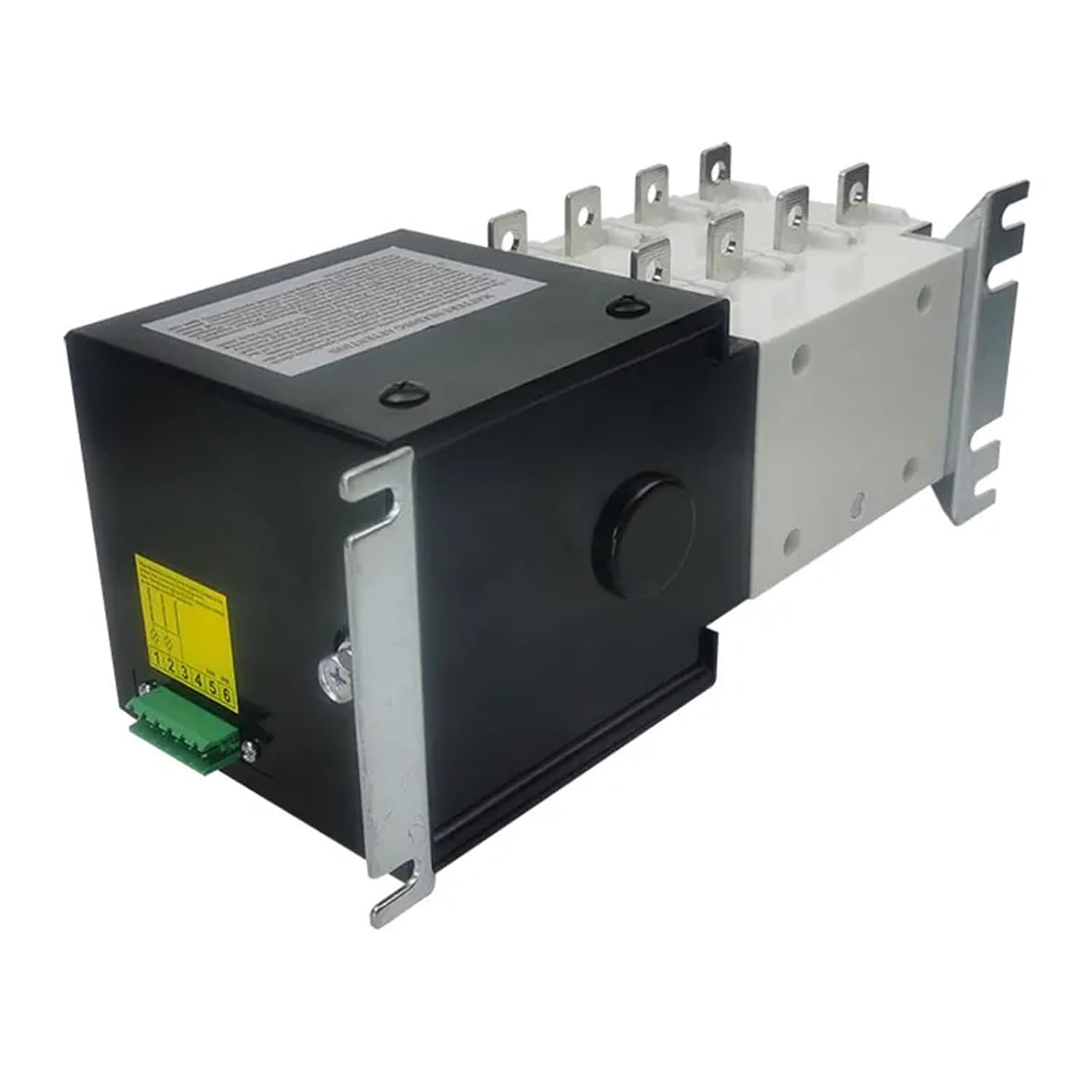
Image 4.4: Side view of the ATS, showing the green terminal block for control wiring connections.
5. Operation
The RP5D-100A ATS offers both automatic and manual modes of operation.

Image 5.1: Angled view of the ATS control panel, showing the mode selector and power source indicators.
5.1 Control Panel Overview
The control panel features:
- Mode Selector Switch: A red switch labeled "AUTO" and "MANU" to select the operating mode.
- Power Source Selector: A rotary switch with positions "ON", "OFF", "II", "I" to select the active power source or turn off the switch.
- Indicators: Lights or markings to indicate which power source is active (I or II).
5.2 Automatic Mode (AUTO)
In AUTO mode, the ATS automatically monitors both power sources and transfers the load when a change in source availability is detected.
- Set the red switch to the "AUTO" position.
- The ATS will automatically select the primary power source (usually utility, indicated by "I").
- If the primary source fails, the ATS will automatically transfer the load to the secondary source (e.g., generator, indicated by "II").
- When the primary source is restored, the ATS will automatically transfer the load back to the primary source after a pre-set delay (if applicable).
5.3 Manual Mode (MANU)
In MANU mode, you can manually select the desired power source using the rotary switch.
- Set the red switch to the "MANU" position.
- Rotate the power source selector switch to "I" to connect to Power Source 1.
- Rotate the power source selector switch to "II" to connect to Power Source 2.
- Rotate the power source selector switch to "OFF" to disconnect both power sources from the load.
6. Maintenance
Regular maintenance ensures the longevity and reliable operation of your ATS.
- Periodic Inspection: Annually inspect the ATS for signs of wear, corrosion, or loose connections.
- Cleaning: Keep the ATS free from dust, dirt, and moisture. Use a dry, lint-free cloth for cleaning. Do not use solvents or abrasive cleaners.
- Connection Checks: Periodically verify that all electrical connections are tight and secure. Loose connections can lead to overheating and failure.
- Functional Test: Periodically test the automatic transfer function by simulating a primary power failure (e.g., by turning off the primary breaker, if safe to do so and with proper precautions).
All maintenance should be performed by qualified personnel with power disconnected.
7. Troubleshooting
If you encounter issues with your RP5D-100A ATS, consider the following troubleshooting steps. For complex issues, contact a qualified electrician.
| Problem | Possible Cause | Solution |
|---|---|---|
| ATS does not transfer automatically | ATS is in Manual mode. No power detected from primary source. Control wiring issue. | Switch to "AUTO" mode. Check primary power source. Inspect control wiring connections. |
| No power to load | Both power sources are off. ATS is in "OFF" position. Loose connections. | Verify both power sources are active. Select "I" or "II" on the rotary switch. Check all power connections. |
| Overheating at terminals | Loose connections. Overload condition. | Tighten all terminal screws. Reduce load or verify load is within ATS rating. |
8. Warranty and Support
For warranty information and technical support, please refer to the documentation provided at the time of purchase or contact your vendor directly. Keep your purchase receipt as proof of purchase.
For further assistance, please contact FRPKPNOX customer service through their official channels.


