1. Introduction
This manual provides essential instructions for the proper installation, operation, and maintenance of the AVLIS-CO EHT-113-01-S-D Connector Header. Please read this manual thoroughly before using the product to ensure safe and efficient operation. Retain this manual for future reference.
2. Product Overview
The AVLIS-CO EHT-113-01-S-D is a high-quality through-hole connector header designed for reliable electrical connections in various electronic applications. It features 26 positions with a 2mm pitch, making it suitable for compact circuit board designs. This component is RoHS compliant, ensuring it meets environmental standards for restricted hazardous substances.
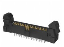
Figure 1: AVLIS-CO EHT-113-01-S-D Connector Header. This image displays the AVLIS-CO EHT-113-01-S-D connector header. It is a black, rectangular component with gold-plated pins visible along its length, designed for through-hole mounting. The connector features two mounting ears on either side.
3. Setup and Installation
Proper installation is crucial for the performance and longevity of the connector header. Follow these guidelines:
- Safety First: Ensure all power to the circuit board is disconnected before handling or installing the connector. Use appropriate anti-static measures to prevent damage to sensitive electronic components.
- Tools Required:
- Soldering iron (temperature controlled)
- Solder (lead-free recommended for RoHS compliance)
- Flux (optional, but recommended for clean joints)
- Desoldering wick or pump (for corrections)
- Magnifying glass or microscope (for inspection)
- Preparation: Verify that the circuit board has the correct footprint for a 26-position, 2mm pitch through-hole header. Clean the solder pads if necessary.
- Mounting: Carefully align the connector header with the corresponding holes on the printed circuit board (PCB). Ensure all pins pass through the holes without bending.
- Soldering: Secure the connector in place, then solder each pin to its respective pad on the PCB. Apply heat to both the pin and the pad simultaneously, then introduce solder. Ensure a good solder joint with proper wetting and no cold joints or solder bridges.
- Inspection: After soldering, visually inspect all joints for quality. Check for any bent pins, short circuits, or insufficient solder.
4. Operating Instructions
Once installed, the EHT-113-01-S-D connector header functions as a passive interface for electrical signals. Its operation involves connecting a mating connector (not included) to establish electrical continuity between two parts of a circuit or between a circuit board and an external device.
- Mating Connector: Ensure the mating connector is compatible with the EHT-113-01-S-D header in terms of pin count, pitch, and mechanical design.
- Connection: Gently align the mating connector with the header and push firmly until it is fully seated. Avoid excessive force to prevent damage to pins or housing.
- Disconnection: To disconnect, pull the mating connector straight away from the header. Do not twist or pull at an angle, as this can bend pins or damage the connector housing.
5. Maintenance
The EHT-113-01-S-D connector header is designed for long-term reliability with minimal maintenance. However, periodic inspection can help ensure optimal performance.
- Cleaning: If dust or debris accumulates, gently clean the connector using a soft brush or compressed air. For stubborn grime, use a lint-free cloth lightly dampened with isopropyl alcohol. Ensure the connector is completely dry before re-applying power.
- Inspection: Periodically check for any signs of physical damage, such as bent or corroded pins, cracked housing, or loose solder joints. Address any issues promptly.
- Environmental Conditions: Ensure the operating environment remains within the specified temperature and humidity ranges to prevent premature wear or failure.
6. Troubleshooting
If you experience issues with the connector, consider the following troubleshooting steps:
- No Electrical Continuity:
- Check if the mating connector is fully seated.
- Inspect for bent or broken pins on both the header and the mating connector.
- Verify solder joint integrity on the PCB. Reflow any suspicious joints.
- Use a multimeter to test continuity across the pins.
- Intermittent Connection:
- Ensure the mating connector is securely latched (if applicable).
- Check for debris or corrosion on the contact surfaces.
- Inspect for hairline cracks in solder joints or the PCB.
- Difficulty Mating/Unmating:
- Verify correct alignment.
- Check for physical obstructions or damage to the connector housing or pins.
- Ensure the mating connector is the correct type and size.
7. Specifications
Refer to the table below for detailed technical specifications of the AVLIS-CO EHT-113-01-S-D Connector Header.
| Specification | Value |
|---|---|
| Model Number | EHT-113-01-S-D |
| Brand | AVLIS-CO |
| Type | Connector Header |
| Mounting Type | Through Hole |
| Number of Positions | 26 |
| Pitch | 2MM |
| Compliance | RoHS |
| ASIN | B0FD35FP36 |
| UPC | 027521184262 |
| Manufacturer | AVLIS-CO |
| Date First Available | June 13, 2025 |
8. Warranty and Support
For information regarding warranty coverage, technical support, or replacement parts for your AVLIS-CO EHT-113-01-S-D Connector Header, please contact AVLIS-CO directly through their official website or customer service channels. Ensure you have your product model number (EHT-113-01-S-D) and purchase details available when contacting support.