1. Introduction
This manual provides essential information for the proper installation, operation, and maintenance of your Pilipane 24V 350W Brushless DC Motor Controller. This controller is designed for electric bicycles and scooters, offering reliable performance and safety features. Please read this manual thoroughly before use to ensure correct application and to prevent damage.
2. Safety Information
- Always disconnect power before performing any installation, maintenance, or troubleshooting.
- Ensure all connections are secure and correctly polarized to prevent short circuits or damage to the controller and other components.
- This controller operates at 24V DC. Do not connect it to higher voltage power sources.
- Avoid exposing the controller to water, excessive moisture, or extreme temperatures.
- Only use this controller with brushless DC motors that are compatible with its specifications.
- Professional installation is recommended if you are unfamiliar with electrical systems.
3. Product Overview
The Pilipane Brushless DC Motor Controller is a high-performance replacement accessory for electric bikes and scooters. It features an aluminum alloy casing for durability and efficient heat dissipation.
Key Features:
- High Performance Protection: Incorporates anti-coaster technology and robust overcurrent protection for smooth and safe operation.
- Automatic Hall Sensor Identification: Automatically identifies the hall sensor and detects 24V voltage for simplified installation.
- Dual Phase Angle Detection: Recognizes both 60-degree and 120-degree phase angles, ensuring broad compatibility.
- EABS Brake System: Provides reliable low-level EABS braking for enhanced safety and control.
- Versatile Compatibility: Suitable for various electric bicycles and scooters.
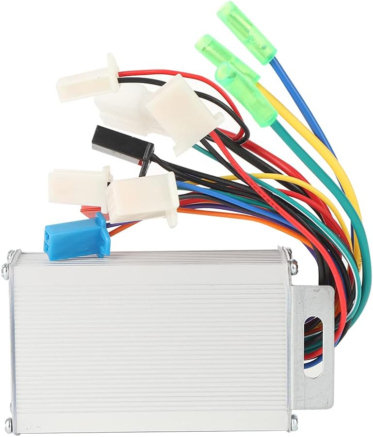
Figure 3.1: Front view of the Pilipane Brushless DC Motor Controller, showing its compact design and wire harness.

Figure 3.2: Angled view of the controller, highlighting the product label with technical details.
4. Setup and Installation
This controller is designed for systems with sensors. Ensure your motor is equipped with Hall sensors for proper operation. This is a simple version controller, focusing on core functionality.
Installation Steps:
- Prepare for Installation: Ensure the electric bike or scooter is powered off and the battery is disconnected.
- Mount the Controller: Securely mount the controller in a suitable location, away from direct moisture and excessive heat. The aluminum alloy casing helps with heat dissipation, but good airflow is still beneficial.
- Connect Power Wires: Connect the main power wires from the battery to the controller. Pay close attention to polarity (positive to positive, negative to negative).
- Connect Motor Wires: Connect the three phase wires from the motor to the corresponding outputs on the controller.
- Connect Hall Sensor Wires: Connect the Hall sensor wires from the motor to the controller. The controller features automatic Hall sensor identification.
- Connect Throttle: Connect the throttle wires to the designated input on the controller.
- Connect Brake Levers: Connect the EABS brake lever wires. This controller supports low-level braking.
- Other Connections: Connect any other necessary accessories such as speed display or power lock, if applicable and supported by the controller.
- Initial Power-Up: After all connections are made and double-checked, reconnect the battery and power on the system. The controller will automatically identify the Hall sensors and 24V voltage.
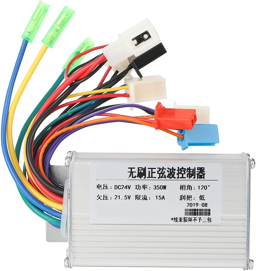
Figure 4.1: Top view illustrating the wire connections for installation.
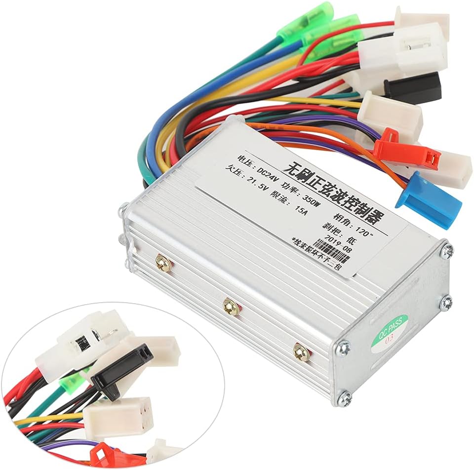
Figure 4.2: Detailed view of the various connectors for power, motor, and sensors.
5. Operating Instructions
Once installed, the controller manages the power delivery to your brushless DC motor based on your throttle input and brake signals.
- Power On: Turn on the main power switch of your electric bike or scooter. The controller will initialize.
- Throttle Control: Gently twist the throttle to accelerate. The controller will regulate motor speed based on your input.
- Braking: Engage the brake levers. The EABS brake system will provide controlled stopping power. The low-level brake signal ensures immediate response.
- Overcurrent Protection: The controller is equipped with overcurrent protection. If an excessive current draw is detected, the controller may temporarily cut power to protect itself and the motor. Reduce load or check for obstructions if this occurs.
6. Maintenance
Regular maintenance ensures the longevity and optimal performance of your motor controller.
- Keep Clean and Dry: Periodically clean the exterior of the controller with a dry cloth. Ensure it remains free from dust, dirt, and moisture.
- Inspect Connections: Regularly check all wire connections for tightness and signs of wear or corrosion. Loose connections can lead to intermittent operation or damage.
- Avoid Physical Damage: Protect the controller from impacts or vibrations that could damage its internal components or casing.
- Temperature Management: Ensure the controller is not operating in excessively hot environments, which can reduce its lifespan. The aluminum alloy casing is designed to help dissipate heat.
7. Troubleshooting
If you encounter issues with your controller, refer to the following common problems and solutions:
| Problem | Possible Cause | Solution |
|---|---|---|
| Motor does not run | No power to controller; Loose connections; Faulty throttle; Motor or Hall sensor issue. | Check battery connection and charge; Inspect all wire connections; Test throttle functionality; Verify motor and Hall sensor integrity. |
| Motor runs erratically or with reduced power | Partial Hall sensor failure; Incorrect phase wire connection; Low battery voltage. | Check Hall sensor connections; Re-verify motor phase wire connections; Charge battery fully. |
| Controller cuts out during operation | Overcurrent protection triggered; Undervoltage protection triggered; Overheating. | Reduce load on motor; Check battery voltage; Ensure adequate ventilation for controller. |
| Brakes not functioning | Brake lever switch faulty; Loose brake wire connection. | Check brake lever functionality; Inspect brake wire connections to controller. |
If problems persist after attempting these solutions, contact customer support.
8. Specifications
| Rated Voltage | DC 24V |
| Rated Power | 350W |
| Current | 16-18A |
| Phase Angle | 120 degrees (compatible with 60 degrees) |
| Undervoltage Protection | 21.5V |
| Limit Current | 15A |
| Brake System | Low-level EABS |
| Material | Aluminum Alloy |
| Weight | Approx. 216g (7.6 ounces) |
| Dimensions | Approx. 9.2 x 5.5 x 3.2 cm (3.6 x 2.2 x 1.3 inches) |
9. Warranty Information
Pilipane products are manufactured to high-quality standards. This product comes with a standard manufacturer's warranty against defects in materials and workmanship under normal use. Please retain your proof of purchase for warranty claims. The warranty does not cover damage caused by improper installation, misuse, neglect, accidents, or unauthorized modifications.
10. Support
For technical assistance, troubleshooting not covered in this manual, or warranty inquiries, please contact Pilipane customer support through the retailer where the product was purchased or visit the official Pilipane website for contact information.