1. Introduction
This manual provides essential information for the safe and efficient installation, operation, and maintenance of your FCNGEVBH ATS 100A 220V Automatic Transfer Switch, Model JTQ3-125. Please read this manual thoroughly before using the product and retain it for future reference. This device is designed to automatically switch between a primary power source (e.g., utility grid) and a secondary power source (e.g., generator) to ensure continuous power supply.
2. Safety Information
WARNING: Electrical shock hazard. Installation and servicing should only be performed by qualified personnel. Failure to follow these instructions may result in serious injury or death.
- Always disconnect all power sources before installing or servicing the transfer switch.
- Ensure proper grounding of the device.
- Verify all wiring connections are secure and correct according to local electrical codes.
- Do not operate the switch if it appears damaged.
- Keep children away from electrical equipment.
- Wear appropriate personal protective equipment (PPE) such as insulated gloves and safety glasses.
3. Product Overview
The FCNGEVBH ATS 100A 220V Automatic Transfer Switch is designed for reliable power source switching. It supports both automatic and manual transfer operations.
3.1 Features
- Automatic and Manual Transfer Modes
- Din Rail Mounted for easy installation
- Dual Power Source Management (City Power / Generator)
- High current capacity: 100A
- Rated for 220V AC systems
3.2 Components
The transfer switch consists of the main switching mechanism, control terminals, and power terminals for connecting the two power sources and the load.
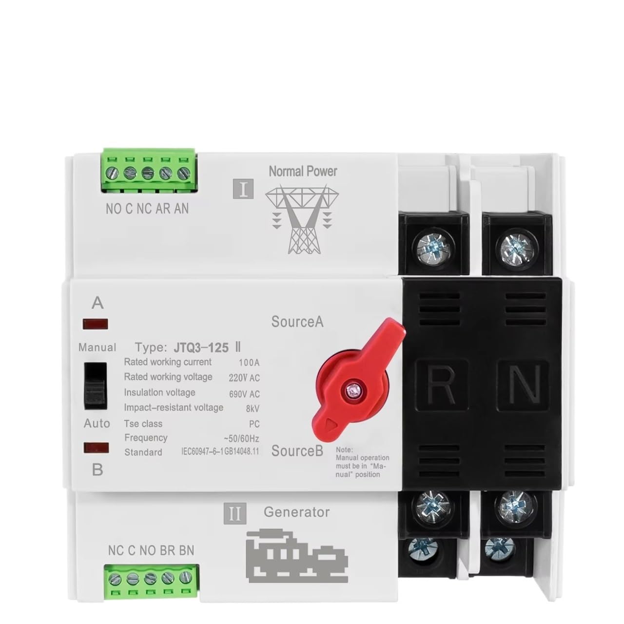
Figure 1: Front view of the FCNGEVBH ATS 100A 220V Automatic Transfer Switch. This image displays the main body of the switch, including the red manual/auto selector handle, the "City Power" (Source A) and "Generator" (Source B) labels, and the control and power terminal blocks.

Figure 2: Top-down view of the transfer switch with example control wiring. Red wires are shown connecting the control terminals, illustrating a typical setup for automatic operation. The main power terminals are also visible.
4. Specifications
| Parameter | Value |
|---|---|
| Model Number | JTQ3-125 |
| Rated Working Current | 100A |
| Rated Working Voltage | 220V AC |
| Insulation Voltage | 690V AC |
| Impact-resistant Voltage | 8kV |
| Tse Class | PC |
| Frequency | 50/60Hz |
| Standard | IEC60947-6-1GB14048.11 |
| Switch Type | Universal Switch |
| Features | Automatic/Manual Transfer |
| Mounting | Din Rail Mounted |
| Approximate Item Weight | 1.76 ounces |
4.1 Dimensions (2P Version)

Figure 3: Dimensions of the 2-pole transfer switch. This image shows the height (98mm/3.86in), width (108mm/4.25in), and depth (71mm/2.79in, 78mm/3.079in including terminals) of the device.

Figure 4: Additional dimension view of the 2-pole transfer switch. This provides another perspective on the device's measurements, confirming the overall size for installation planning.
5. Setup and Installation
Important: All installation work must be performed by a qualified electrician in accordance with all national and local electrical codes.
- Power Disconnection: Ensure all power sources (utility grid and generator) are completely disconnected and locked out before beginning installation.
- Mounting: Mount the ATS on a standard Din Rail within an appropriate electrical enclosure. Ensure adequate ventilation and clearance for wiring.
- Wiring Connections:
- Connect the primary power source (e.g., City Power) to the "Source A" terminals.
- Connect the secondary power source (e.g., Generator) to the "Source B" terminals.
- Connect the load (circuits to be powered) to the output terminals of the ATS.
- Connect the control wiring as per the wiring diagram (refer to Figure 2 for an example of control signal connections). Ensure correct polarity for control signals.
- Grounding: Properly ground the transfer switch according to local electrical codes.
- Verification: Double-check all connections for tightness and correctness. Ensure no bare wires are exposed.
6. Operating Instructions
The FCNGEVBH ATS supports both automatic and manual operation modes.
6.1 Automatic Mode
- Ensure the manual/auto selector switch (red handle) is set to the "Auto" position.
- When the primary power source (Source A) is present, the switch will automatically connect the load to Source A.
- If Source A fails, the switch will detect the power loss and, after a pre-set delay (if configured externally), initiate the transfer to Source B (Generator). The generator must be started and stable for the transfer to occur.
- When Source A is restored, the switch will detect its return and, after a pre-set delay, transfer the load back to Source A.
6.2 Manual Mode
Manual operation allows you to physically select the desired power source.
- To operate manually, move the red selector handle to the "Manual" position.
- Once in manual mode, you can physically move the switch lever to select "Source A" or "Source B" as needed.
- Caution: Ensure the selected source is stable and safe before transferring the load manually.
- To return to automatic operation, move the red selector handle back to the "Auto" position.
7. Maintenance
Regular maintenance helps ensure the longevity and reliable operation of your ATS.
- Periodic Inspection: Annually inspect the transfer switch for any signs of physical damage, loose connections, or overheating.
- Cleaning: Keep the unit clean and free from dust and debris. Use a dry, soft cloth for cleaning. Do not use liquid cleaners.
- Terminal Check: Periodically check all terminal connections for tightness. Loose connections can cause overheating and potential failure.
- Functionality Test: It is recommended to periodically test the automatic transfer function by simulating a power outage (if safe and feasible) to ensure the system operates as expected.
- Professional Service: For any complex issues or internal component inspection, contact a qualified electrician.
8. Troubleshooting
This section provides solutions to common issues. For problems not listed here, contact a qualified technician.
| Problem | Possible Cause | Solution |
|---|---|---|
| Switch does not transfer automatically. |
|
|
| No power to load after transfer. |
|
|
| Overheating of terminals. |
|
|
9. Warranty and Support
Specific warranty information for the FCNGEVBH ATS 100A 220V Automatic Transfer Switch is typically provided at the point of purchase or within separate documentation. Please refer to your purchase receipt or contact the retailer for details regarding warranty coverage.
For technical support or service inquiries, please contact your supplier or the manufacturer directly. Ensure you have your product model number (JTQ3-125) and purchase details available when seeking support.