Introduction
This manual provides essential information for the safe and correct installation, operation, and maintenance of your new Generic Spindle Assembly Replacement Part. Please read these instructions thoroughly before beginning any work to ensure proper function and longevity of the part. This replacement part is designed for specific Snapper and Simplicity lawn mower models.
Safety Information
- Always wear appropriate personal protective equipment (PPE), including safety glasses and gloves, when handling or installing the spindle assembly.
- Ensure the lawn mower is turned off, the engine is cool, and the spark plug wire is disconnected before performing any maintenance or installation.
- Use only the correct tools for installation to prevent damage to the part or injury.
- If you are unsure about any step, consult a qualified service technician.
Compatibility
This spindle assembly is a replacement part compatible with various Snapper and Simplicity lawn mower models. Please verify your original part number against the following:
- Snapper/Simplicity Original Part Numbers: 2691137-00, 2691161-00, 2691357-01, Spindlepart#528074
- Manufacturer Part Numbers: 1735326YP, 1735573YP, 1735323YP, 1735328YP, 1735326YP-A, 1735573YP-A, 7502226YP, 7600211YP, 84003175, 330240B
It is crucial to compare your existing spindle assembly with the images and specifications provided in this manual to ensure a correct fit.
Package Contents
The package includes one (1) set of the Spindle Assembly Replacement Part. Please inspect the contents upon arrival to ensure all components are present and undamaged.
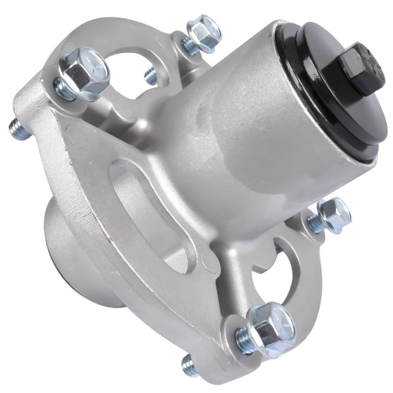
Image 1: Overall view of the Generic Spindle Assembly Replacement Part. This image shows the complete assembly with mounting bolts.
Setup and Installation
Follow these steps carefully for proper installation of the spindle assembly. Refer to your lawn mower's specific service manual for detailed instructions on deck removal and reassembly.
- Preparation: Park the lawn mower on a flat, stable surface. Turn off the engine, remove the ignition key, and disconnect the spark plug wire to prevent accidental starting. Allow the engine and deck to cool.
- Deck Removal: Carefully remove the mower deck from the lawn mower chassis according to your mower's manufacturer instructions. Place the deck on a clean, stable workbench.
- Old Spindle Removal: Locate the faulty spindle assembly. Remove the blade from the bottom of the spindle shaft. Then, unbolt the spindle assembly from the top of the mower deck. Note the orientation of any spacers or washers.
- New Spindle Installation: Position the new Generic Spindle Assembly onto the mower deck, ensuring the mounting holes align correctly.
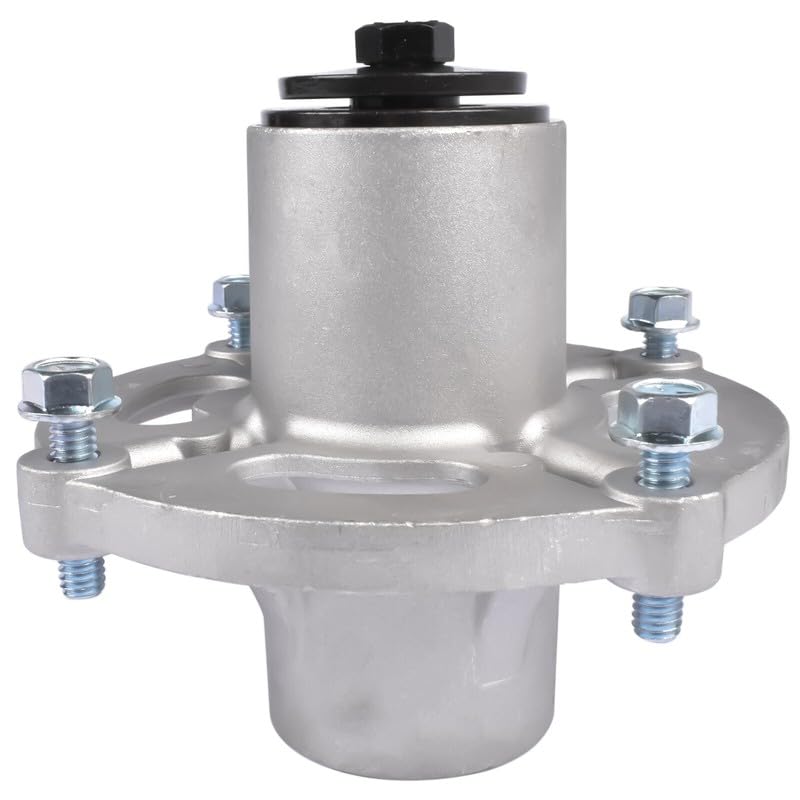
Image 2: Top view of the spindle assembly, highlighting the four mounting holes for attachment to the mower deck.
- Secure the Spindle: Insert the mounting bolts through the spindle assembly and the deck. Tighten the bolts evenly and securely to the manufacturer's recommended torque specifications (if available).
- Blade Attachment: Attach the mower blade to the bottom of the new spindle shaft. Ensure the blade is oriented correctly (cutting edge facing down) and the blade bolt is tightened to the manufacturer's specifications.
- Deck Reinstallation: Reinstall the mower deck onto the lawn mower chassis, following your mower's manufacturer instructions. Reconnect all belts and linkages.
- Final Checks: Reconnect the spark plug wire. Before starting the engine, manually rotate the blades to ensure they spin freely and do not contact the deck or any other components.
Operating
Once the spindle assembly is correctly installed, the lawn mower can be operated as usual. Listen for any unusual noises or vibrations during the first few uses, which could indicate an installation issue.
Maintenance
Regular maintenance will extend the life of your spindle assembly.
- Lubrication: This spindle assembly features a grease fitting for lubrication. Apply a small amount of appropriate grease (e.g., lithium-based grease) using a grease gun every 25 hours of operation or annually, whichever comes first. Do not over-grease.
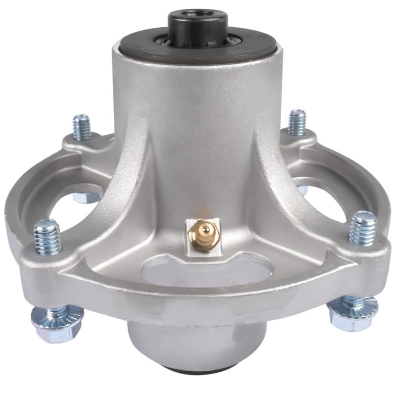
Image 3: Bottom view of the spindle assembly, clearly showing the brass grease fitting for lubrication.
- Inspection: Periodically inspect the spindle assembly for any signs of wear, damage, or loose bolts. Tighten any loose fasteners.
- Cleaning: Keep the area around the spindle assembly clean of grass clippings and debris to prevent buildup and ensure proper function.
Troubleshooting
If you encounter issues after installing the spindle assembly, refer to the table below:
| Problem | Possible Cause | Solution |
|---|---|---|
| Excessive vibration | Improper blade installation; Loose mounting bolts; Damaged blade | Check blade balance and tightness; Tighten spindle mounting bolts; Replace damaged blade |
| Unusual noise from deck | Lack of lubrication; Loose components; Bearing wear | Apply grease to fitting; Check all fasteners; If noise persists, bearing may be worn (replace spindle) |
| Blade not spinning freely | Obstruction; Incorrect installation | Remove debris; Recheck installation steps, especially blade attachment |
Specifications
Key specifications for the Generic Spindle Assembly Replacement Part:
- Part Type: Mower Parts, Spindles, Spindle Assembly
- Model Number: Spindlepart#527080
- Compatible with: Snapper, Simplicity (various models, see compatibility section)
- Includes: Grease fitting for lubrication
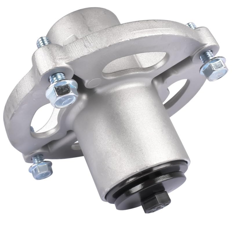
Image 4: Angled view of the spindle assembly, providing another perspective of its construction and mounting points.
Warranty Information
Specific warranty details for this Generic Spindle Assembly Replacement Part are not provided in the product information. Please refer to the retailer or manufacturer for any applicable warranty terms and conditions.
Support
For technical assistance or further inquiries regarding this replacement part, please contact the retailer from whom the product was purchased. No specific manufacturer support contact information is available in the provided product details.