1. Introduction
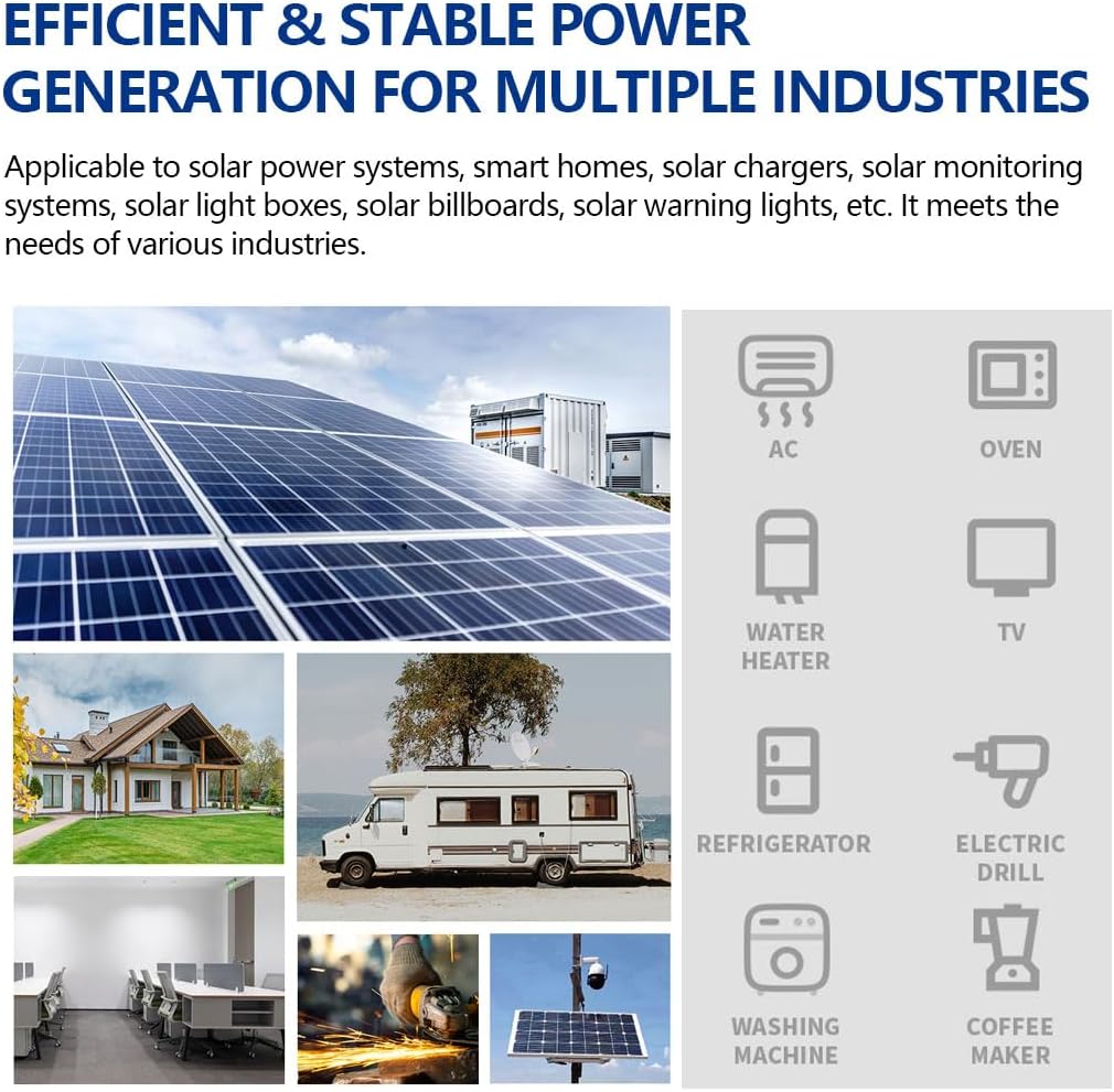
This manual provides detailed instructions for the installation, operation, maintenance, and troubleshooting of your Y&H 120A MPPT Solar Charger Controller. Please read this manual thoroughly before installation and use to ensure optimal performance and safety. This controller is designed for off-grid solar power systems, efficiently managing power flow from solar panels to batteries and loads.
2. Safety Information
Please observe the following safety precautions to prevent personal injury or damage to the controller and other components:
- Ensure all wiring is performed by qualified personnel and complies with local electrical codes.
- Always disconnect the solar panel array and battery power before installing or adjusting the controller.
- Do not disassemble the controller. There are no user-serviceable parts inside.
- Install the controller in a well-ventilated area, away from flammable materials and direct sunlight.
- Wear appropriate personal protective equipment, including insulated gloves and eye protection, during installation.
- Ensure correct polarity when connecting batteries and solar panels. Incorrect polarity can cause severe damage.
- The battery terminals should be installed with fuse protection, and the installation distance should not exceed 150mm.
3. Product Overview
The Y&H 120A MPPT Solar Charger Controller is an advanced Maximum Power Point Tracking (MPPT) device designed to maximize power harvest from your solar array. It features automatic battery voltage recognition and compatibility with various battery types.
3.1 Key Features
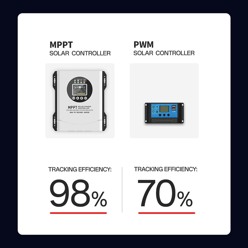
- MPPT Technology: Up to 99% tracking efficiency, 98% conversion efficiency.
- Wide Voltage Range: Supports 24V, 36V, 48V, 60V, 72V, 84V, 96V battery systems with automatic recognition.
- Battery Compatibility: Gel, Flooded, Lithium (LiFePO4), and Ternary Lithium batteries.
- Comprehensive Protections: Overcurrent, overvoltage, undervoltage, high-temperature, and short-circuit protection.
- LCD Display: Provides real-time system status and operational data.
- Connectivity: RS485/Wi-Fi/Wireless monitoring options.
3.2 Controller Components

This image displays the Y&H MPPT Solar Charge Controller, highlighting its key external components. These include the LCD display for system monitoring, the SET button for configuration, SCROLL DOWN and SCROLL UP buttons for navigation, the ESC button to exit menus, and the CONNECTION AREA at the bottom for wiring inputs and outputs.

A closer view of the controller's LCD screen and feedback buttons. The LCD provides clear, intuitive visuals for settings and real-time data. The buttons (ESC, Up, Down, SET) allow for one-touch operation and navigation through the display menus.
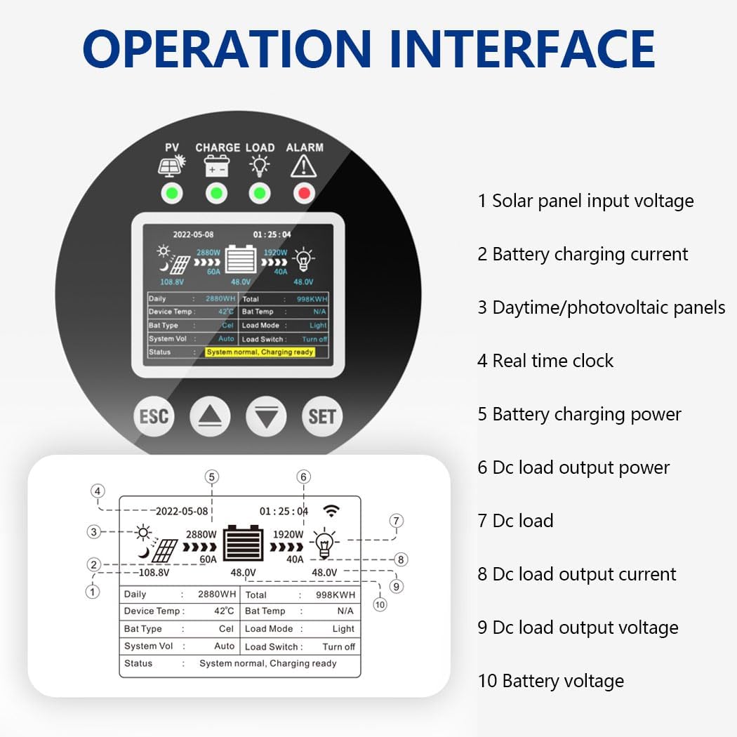
3.3 Operation Interface
This diagram illustrates the various data points displayed on the controller's LCD screen. Key indicators include: 1. Solar panel input voltage, 2. Battery charging current, 3. Daily/total photovoltaic panel power, 4. Real-time clock, 5. Battery charging power, 6. DC load output power, 7. DC load status, 8. DC load output current, 9. DC load output voltage, and 10. Battery voltage. This interface allows for comprehensive monitoring of the system's performance.
4. Setup and Installation
4.1 Mounting the Controller
- Choose a dry, well-ventilated location, protected from direct sunlight, high temperatures, and moisture.
- Ensure adequate clearance around the controller for proper heat dissipation, especially for the cooling fan.
- Mount the controller vertically on a non-flammable surface using appropriate fasteners.
4.2 Wiring Connection Sequence
It is critical to follow the connection sequence below to prevent damage to the controller or other components.

This image illustrates the correct four-step connection sequence for the solar charge controller. Step 1: Connect the Battery, ensuring fuse protection and proper distance. Step 2: Connect the Solar Panel. Step 3: Controller Power On, verify display functionality. Step 4: Connect the Load. This sequence is crucial for safe and correct system startup.
- Connect the Battery: Connect the battery cables to the controller's battery terminals. Ensure correct polarity (+ to + and - to -). The battery terminals should be installed with fuse protection, and the installation distance should not exceed 150mm.
- Connect the Solar Panel: Connect the solar panel array cables to the controller's PV input terminals. Ensure correct polarity.
- Controller Power On: After connecting the battery and solar panel, the controller will power on. Observe the display screen. If it does not work or displays abnormally, refer to the troubleshooting guide.
- Connect the Load: Connect the DC load cables to the controller's load terminals. Ensure correct polarity.
Note: If you need to connect a high-power inverter, please connect the inverter directly to the battery, not to the load terminals of the controller.
4.3 Concealed Installation Wiring
This image demonstrates the concealed wiring design of the controller. To access the wiring terminals, simply flip open the bottom cover. After connecting the wires and tightening the screws, close the bottom cover to ensure a neat and secure installation.
4.4 Cooling System
The controller incorporates a high-efficiency cooling fan system. Utilizing advanced aerodynamic design, these fans quickly dissipate heat from inside the controller, ensuring stable and reliable operation even in high-temperature environments.
5. Operating Instructions
5.1 LCD Display Navigation
Use the ESC, Up, Down, and SET buttons to navigate through the LCD display menus and adjust settings. The display provides real-time information on PV input, battery status, load status, and system parameters.
5.2 Battery Type Setting
The controller automatically recognizes 24V-96V battery systems. However, for optimal charging, it is important to select the correct battery type (Gel, Flooded, Lithium) in the settings menu if your battery is not automatically detected or if you wish to fine-tune charging parameters. Refer to the detailed settings menu in the full product manual for specific steps.
5.3 Monitoring Data
The LCD display allows you to monitor various system parameters:
- PV Voltage and Current
- Battery Voltage and Charging Current
- Load Voltage and Current
- Daily and Total Power Generation (kWh)
- Controller Temperature
For remote monitoring, utilize the RS485/Wi-Fi/Wireless connectivity options as per the instructions provided with the respective communication modules.
6. Maintenance
Regular maintenance ensures the longevity and optimal performance of your solar charge controller.
- Cleaning: Periodically clean the controller's exterior with a dry cloth. Ensure the cooling fan vents are free from dust and debris.
- Connection Checks: Annually inspect all wiring connections to ensure they are tight and free from corrosion. Loose connections can cause overheating and system inefficiency.
- Environmental Check: Ensure the installation environment remains dry and well-ventilated.
- Firmware Updates: Check the manufacturer's website for any available firmware updates that may improve performance or add features.
7. Troubleshooting
This section addresses common issues you might encounter with your solar charge controller.
| Problem | Possible Cause | Solution |
|---|---|---|
| Controller not powering on | Battery not connected or low voltage; incorrect battery polarity; loose connections. | Check battery connections and voltage. Ensure correct polarity. Tighten all connections. |
| No charging current from PV | Solar panels not connected; insufficient sunlight; PV array voltage too low/high; PV polarity reversed. | Check PV connections and polarity. Ensure adequate sunlight. Verify PV array voltage is within controller's operating range. |
| Load not working | Load not connected; load overcurrent; battery low voltage; load output disabled. | Check load connections. Reduce load. Charge battery. Enable load output in settings. |
| High temperature alarm | Poor ventilation; excessive ambient temperature; heavy load. | Ensure adequate airflow around the controller. Reduce ambient temperature if possible. Reduce load. |
For issues not listed here, or if troubleshooting steps do not resolve the problem, please contact Y&H customer support.
8. Specifications
| Feature | Specification |
|---|---|
| Model Name | HMW12096-HV-W-I FI |
| Max Input PV Voltage | 480V |
| Max Charging Current | 120A |
| Battery Voltage | 24V/36V/48V/60V/72V/84V/96V Auto Recognition |
| Battery Types | Sealed, Gel, Flooded Lead-Acid, LiFePO4, Lithium |
| MPPT Tracking Efficiency | ≥99% |
| Conversion Efficiency | Up to 98% |
| Max PV Input Power | 480W-11.5kW (depending on system voltage) |
| Item Weight | 10.67 pounds |
| Package Dimensions | 12.59 x 10.55 x 4.01 inches |
| Included Components | Solar Charge Controller body |
| Connectivity | RS485/Wi-Fi/Wireless |
9. Warranty and Support
Y&H products are designed for reliability and performance. For warranty information, technical support, or service inquiries, please refer to the warranty card included with your product or visit the official Y&H website. Please have your model number (HMW12096-HV-W-I FI) and purchase details ready when contacting support.
For additional resources and product information, you may visit the Y&H Store on Amazon.


