1. Introduction
The ZLLJMETER ZL122 is a 9999 counts handheld digital multimeter designed for accurate and reliable measurement of various electrical parameters. This device is suitable for both household and professional use, offering functions such as AC/DC voltage, current, resistance, capacitance, frequency, temperature, diode test, continuity, NCV (Non-Contact Voltage), and live wire detection.
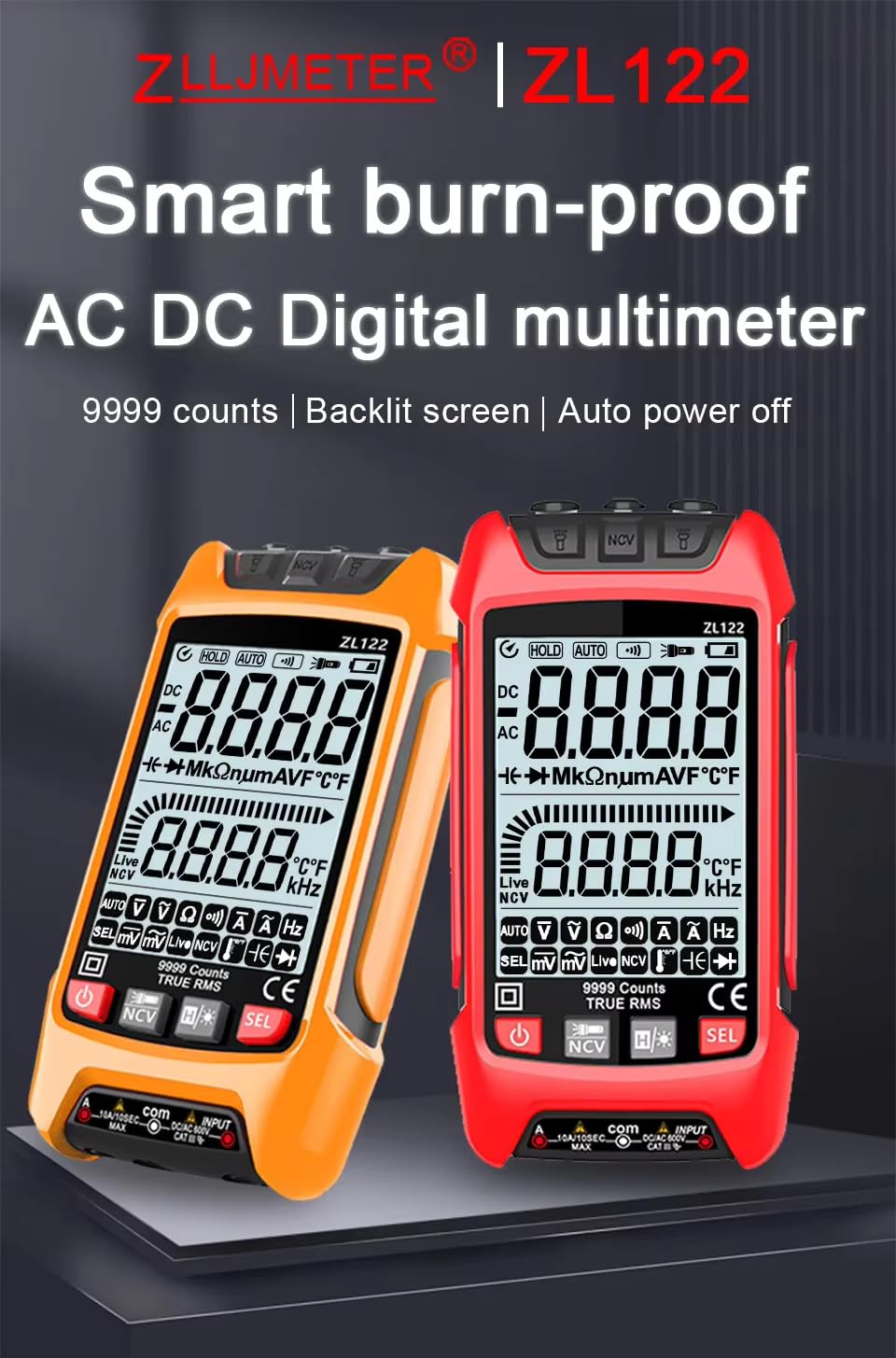
Figure 1: ZLLJMETER ZL122 Digital Multimeter Overview
2. Safety Information
Before using the ZLLJMETER ZL122 multimeter, please read and understand all safety information. Failure to follow these instructions may result in electric shock, fire, or damage to the meter. This device complies with IEC 61010-1 safety standards.
- Always ensure the test leads are in good condition and properly connected before taking measurements.
- Do not measure voltages or currents exceeding the specified maximum limits.
- Exercise extreme caution when working with live circuits.
- Do not use the meter if it appears damaged or if the battery cover is not properly closed.
- Replace batteries when the low battery indicator appears to ensure accurate readings.
- The device features a built-in fuse (10A/250V) to prevent short circuit burn. Do not attempt to bypass or replace with an incorrect fuse type.

Figure 2: Internal Components and Safety Features
3. What's in the Box
Upon opening the package, verify that all the following items are included:
- 1 x ZLLJMETER ZL122 Digital Multimeter
- 1 x User Manual
- 2 x 1.5V AAA Batteries
- 1 x Test Lead Set (Red and Black)
- 1 x Thermocouple (for temperature measurement)
4. Product Overview
Familiarize yourself with the components and controls of your ZLLJMETER ZL122 multimeter:
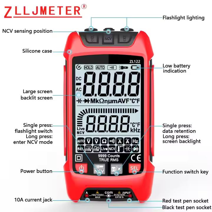
Figure 3: Multimeter Front Panel and Controls
- NCV Sensing Position: Used for non-contact voltage detection.
- Flashlight Lighting: Provides illumination in dark environments.
- Low Battery Indication: Alerts when batteries need replacement.
- Large Screen Backlit Screen: Displays measurements clearly, with backlight for low-light conditions.
- Power Button: Turns the device on or off.
- Function Switch Key (SEL): Cycles through different measurement modes within a function.
- Hold Button: Short press to retain data on the screen. Long press to activate screen backlight.
- Flashlight Button: Short press to turn on/off the flashlight. Long press to enter NCV mode.
- 10A Current Jack: Input for high current measurements.
- Red Test Pen Socket: Positive input for test leads.
- Black Test Pen Socket (COM): Common/Negative input for test leads.
5. Setup
5.1 Battery Installation
- Ensure the multimeter is powered off.
- Locate the battery compartment on the back of the device.
- Open the battery compartment cover.
- Insert two 1.5V AAA batteries, observing the correct polarity (+/-).
- Close the battery compartment cover securely.
5.2 Connecting Test Leads
- Insert the black test lead into the 'COM' (Common) jack.
- For most measurements (voltage, resistance, continuity, capacitance, frequency, temperature, diode), insert the red test lead into the 'VΩmA' jack.
- For high current measurements (up to 10A), insert the red test lead into the '10A' jack.
6. Operating Instructions
6.1 Power On/Off and Basic Functions
- Power On: Press the power button (U) to turn on the multimeter.
- Power Off: Press and hold the power button (U) to turn off the multimeter. The device also features an auto power-off function to conserve battery.
- Auto Range: The ZL122 automatically selects the appropriate measurement range for most functions.
- Data Hold: Short press the 'HOLD' button to freeze the current reading on the display. Press again to release.
- Screen Backlight: Long press the 'HOLD' button to turn the screen backlight on or off.
- Flashlight: Short press the flashlight button to turn the top dual torch lighting on or off. This is useful for working in dimly lit areas.
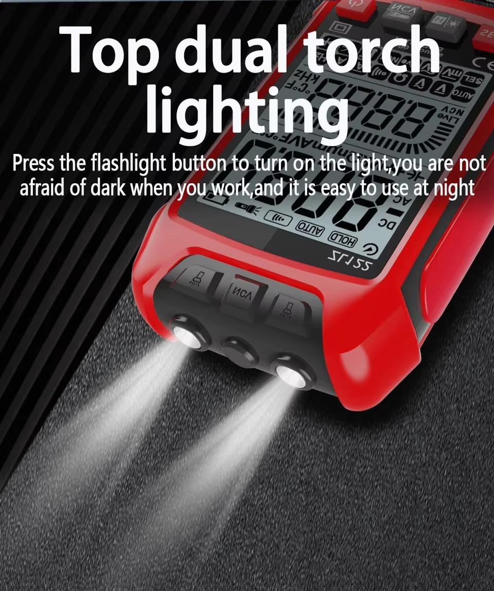
Figure 4: Top Dual Torch Lighting
6.2 Measurement Functions
Use the Function Switch Key (SEL) to cycle through different measurement modes as needed.
AC Voltage Measurement
Connect the test leads in parallel to the AC voltage source. The multimeter will automatically identify and measure AC voltage. For typical household voltage, the reading should be around 220V (depending on region).

DC Voltage Measurement
Connect the red test lead to the positive pole and the black test lead to the negative pole of the DC voltage source. The multimeter automatically recognizes and measures DC voltage.
Resistance Measurement
Ensure the circuit is de-energized. Connect the test leads across the component to measure its resistance. The multimeter automatically recognizes and measures resistance.
Diode Test
Ensure the circuit is de-energized. Connect the red test lead to the anode and the black test lead to the cathode of the diode. The multimeter automatically recognizes and tests the diode.
Continuity (Buzzer) Test
Ensure the circuit is de-energized. Connect the test leads across the circuit or component. If continuity exists (low resistance), the multimeter will emit a beeping sound.

Temperature Measurement
Connect the thermocouple to the multimeter's input jacks. Place the thermocouple tip on or near the object whose temperature you wish to measure. The display will show the temperature in Celsius or Fahrenheit.
Capacitance Measurement
Ensure the capacitor is fully discharged before testing. Connect the test leads to the terminals of the capacitor. The multimeter will display the capacitance value.
NCV (Non-Contact Voltage) Sensing
Long press the flashlight button to enter NCV mode. Bring the NCV sensing position of the multimeter close to an AC voltage source. The device will indicate the presence of AC voltage without direct contact, enhancing safety.
6.3 Live Wire (Zero FireWire) Test
To identify live and neutral wires:
- Adjust the multimeter to the 'Live' gear (often indicated by a lightning bolt symbol or 'Live' on the display).
- Insert the red test pen into the rightmost socket of the power outlet.
- If the screen turns red, the arrow signal is full, and the buzzer sounds, it indicates a live wire.
- If the screen does not turn red, there is no signal, and no beeping sound, it indicates a neutral (zero) line.

Figure 5: Live Wire Detection
7. Maintenance
7.1 Battery Replacement
When the low battery indicator appears on the display, replace the batteries immediately to ensure accurate measurements. Refer to Section 5.1 for battery installation instructions.
7.2 Cleaning
Wipe the meter with a damp cloth and mild detergent. Do not use abrasives or solvents. Ensure the meter is completely dry before use.
7.3 Fuse Replacement
The multimeter contains a 10A/250V fuse. If the current measurement function stops working, the fuse may need replacement. This should only be performed by qualified personnel. Ensure the replacement fuse matches the original specifications.
8. Troubleshooting
- Meter does not power on: Check battery installation and ensure batteries are not depleted. Replace if necessary.
- No reading or 'OL' displayed: Ensure test leads are properly connected to the meter and the circuit. The 'OL' (Overload) indication means the measured value exceeds the selected range; the auto-ranging feature should typically handle this, but ensure you are not attempting to measure beyond the meter's maximum capabilities.
- Inaccurate readings: Check battery level. Ensure test leads are making good contact. Verify the correct measurement function is selected.
- Current measurement not working: Check the 10A/250V fuse.
9. Specifications
The following table details the technical specifications of the ZLLJMETER ZL122 Digital Multimeter:

Figure 6: ZL122 Detailed Specifications
| Parameter | Range | Accuracy | Resolution |
|---|---|---|---|
| AC Voltage | 600.0mV/9.999V/99.99V/999.9V | ±(0.8%+5) | 0.1mV/0.001V/0.01V/0.1V |
| DC Voltage | 600.0mV/9.999V/99.99V/999.9V | ±(0.5%+3) | 0.1mV/0.001V/0.01V/0.1V |
| AC Current | 999.9mA/10A | ±(1.0%+8) | 1mA/0.01A |
| DC Current | 999.9mA/10A | ±(1.0%+5) | 1mA/0.01A |
| Resistance | 999.9Ω/9.999kΩ/99.99kΩ/999.9kΩ/9.999MΩ/99.99MΩ | ±(0.8%+3) | 0.1Ω/0.001kΩ/0.01kΩ/0.1kΩ/0.001MΩ/0.01MΩ |
| Capacitance | 9.999nF/999.9nF/9.999uF/99.99uF/999.9uF/9.999mF/99.99mF | ±(10.0%+40) for 9.999nF, ±(2.5%+20) for others | 0.001nF/0.1nF/0.001uF/0.01uF/0.1uF/1uF/0.01mF |
| Temperature | -40℃~1000℃ (-40℉~1832℉) | ±(1%+3) | 1℃/1℉ |
| Frequency | 100Hz/1000Hz | ±(1.0%+5) | 0.1Hz/1Hz |
| Display | 9999 Counts LCD with Backlight | ||
| Power Source | 2 x 1.5V AAA Batteries | ||
| Dimensions (LxWxH) | 11.8 x 6 x 2.04 cm | ||
| Weight | 350 Grams | ||
| Safety Rating | IEC 61010-1 | ||
10. Warranty and Support
The ZLLJMETER ZL122 Digital Multimeter comes with a 1 Year Warranty from the date of purchase.
For technical support, warranty claims, or any inquiries, please contact the importer:
MDS Automech Solutions
Q-106, Phase 3, Shivalik Nagar, BHEL,
Haridwar, Uttarakhand-249403, India
Contact: +91-9870694636
Email: mohit@mdsautomech.in