1. Product Overview
The ZLLJMETER ZL128B is a smart digital multimeter designed for accurate electrical measurements. It features a 9999-count LCD display with backlight, auto-ranging capabilities, and a rechargeable lithium battery for extended use. This device integrates multiple functions including AC/DC voltage, resistance, frequency, capacitance, diode test, and non-contact voltage (NCV) detection.
Key Features:
- 9999 Counts LCD Display
- Auto Range Functionality
- Live Wire Test
- Non-Contact Voltage (NCV) Detection
- Diode Test and On-off Beep
- Data Hold Function
- True RMS Measurement
- Automatic Power Off
- Integrated Flashlight
- Rechargeable Lithium Battery
- Capacitance Measurement up to 100mF
- Frequency Measurement up to 10MHz
- Temperature Measurement (-50°C to 1100°C industrial, 0°C to 60°C ambient)

Figure 1: ZLLJMETER ZL128B Digital Multimeter with included accessories.

Figure 2: The ZL128B features a large, backlit color display for clear readings in various lighting conditions.
2. Safety Information
WARNING: Read and understand all safety information and operating instructions in this manual before using the ZL128B multimeter. Failure to follow these instructions may result in electric shock, fire, or serious injury.
- Always ensure the multimeter is in the correct measurement mode before connecting test leads to a circuit.
- Do not exceed the maximum input values specified for each range.
- Never use the multimeter if it appears damaged or if the test leads are compromised.
- Avoid touching exposed wires or circuit components while taking measurements.
- Use caution when working with voltages above 30V AC RMS, 42V peak, or 60V DC, as these pose a shock hazard.
- Always disconnect power to the circuit before measuring resistance, capacitance, or continuity.
- Ensure the battery is adequately charged for accurate readings.
- This device complies with IEC 61010-1 safety standards.
3. Setup
3.1 Unpacking and Inspection
Carefully unpack the ZL128B multimeter and all accessories. Verify that all items listed below are present and undamaged:
- ZLLJMETER ZL128B Digital Multimeter
- Test Leads (Red and Black)
- USB Charging Cable
- Thermocouple (for temperature measurement)
- User Manual (this document)
If any items are missing or damaged, contact your supplier immediately.
3.2 Charging the Battery
The ZL128B is equipped with a rechargeable lithium battery. Before first use, or if the battery indicator shows low power, charge the device using the provided USB cable.
- Connect the small end of the USB charging cable to the charging port on the multimeter.
- Connect the standard USB end of the cable to a USB power adapter (not included) or a computer USB port.
- The charging indicator on the multimeter will show the charging status.
- Once fully charged, disconnect the USB cable.
The multimeter can be used while charging, but it is recommended to charge it fully before critical measurements.
3.3 Connecting Test Leads
Always ensure test leads are correctly connected for the desired measurement function.
- For most measurements (Voltage, Resistance, Capacitance, Frequency, Diode, Continuity):
- Insert the red test lead into the "VΩHz" input jack.
- Insert the black test lead into the "COM" input jack.
- For Current Measurements (AC/DC Current):
- Insert the red test lead into the "10A" input jack.
- Insert the black test lead into the "COM" input jack.
4. Operating Instructions
The ZL128B features an intelligent auto-ranging function that simplifies operation for common measurements. For specific functions, manual mode selection may be required.
4.1 Power On/Off
Press the power button to turn the multimeter on. The device will automatically enter auto-ranging mode. To turn off, press and hold the power button, or wait for the automatic power-off feature to activate after a period of inactivity.
4.2 Function Selection (SEL Button)
In auto mode, the multimeter attempts to identify the measurement type. For specific functions or to cycle through sub-functions within a mode (e.g., AC/DC voltage, diode/continuity), press the SEL button.
4.3 AC/DC Voltage Measurement
The ZL128B can measure both AC and DC voltages. In auto mode, it will detect the type of voltage. For manual selection, use the SEL button.
- Connect the red test lead to the "VΩHz" jack and the black test lead to the "COM" jack.
- Turn on the multimeter. It will typically default to auto voltage detection.
- Touch the red and black test probes to the points in the circuit where you want to measure voltage.
- Read the voltage value displayed on the screen.
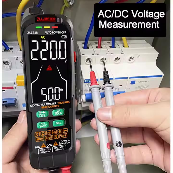
Figure 3: Measuring AC/DC Voltage. Ensure test leads are connected to the correct ports.
4.4 AC/DC Current Measurement
To measure current, the multimeter must be connected in series with the circuit. Always ensure the circuit is de-energized before connecting the multimeter for current measurement.
- De-energize the circuit.
- Connect the red test lead to the "10A" jack and the black test lead to the "COM" jack.
- Break the circuit at the point where you want to measure current.
- Connect the red probe to the higher potential side and the black probe to the lower potential side to complete the circuit through the multimeter.
- Re-energize the circuit.
- Read the current value displayed on the screen.
- De-energize the circuit before disconnecting the multimeter.
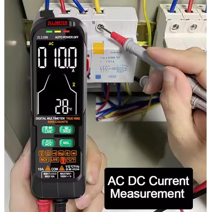
Figure 4: Measuring AC/DC Current. Connect the multimeter in series with the circuit.
4.5 Resistance Measurement
To measure resistance, the component must be isolated from the circuit (de-energized and disconnected).
- Connect the red test lead to the "VΩHz" jack and the black test lead to the "COM" jack.
- Select the resistance mode (Ω) using the SEL button if not in auto mode.
- Touch the test probes across the component to be measured.
- Read the resistance value.
4.6 Capacitance Measurement
WARNING: Ensure capacitors are fully discharged before measuring capacitance to prevent damage to the multimeter.
- Connect the red test lead to the "VΩHz" jack and the black test lead to the "COM" jack.
- Select the capacitance mode (F) using the SEL button.
- Touch the test probes across the capacitor terminals.
- Read the capacitance value.

Figure 5: Measuring Capacitance. Always discharge capacitors before measurement.
4.7 Frequency Measurement
The ZL128B can measure the frequency of AC signals.
- Connect the red test lead to the "VΩHz" jack and the black test lead to the "COM" jack.
- Select the frequency mode (Hz) using the SEL button.
- Touch the test probes across the signal source.
- Read the frequency value.
4.8 Diode Test and Continuity
These functions are typically grouped. Use the SEL button to switch between them.
- Diode Test:
- Connect the red test lead to the "VΩHz" jack and the black test lead to the "COM" jack.
- Select the diode test mode (symbol: →|→).
- Place the red probe on the anode and the black probe on the cathode of the diode. A forward voltage drop will be displayed. Reverse the probes; an open circuit (OL) should be displayed.
- Continuity Test:
- Connect the red test lead to the "VΩHz" jack and the black test lead to the "COM" jack.
- Select the continuity mode (symbol: ♫).
- Touch the probes to the two points to be tested. If continuity exists (resistance below a certain threshold), the multimeter will emit an audible beep.
4.9 Non-Contact Voltage (NCV) Detection
The NCV function allows detection of AC voltage without direct contact with conductors.
- Press the NCV button to activate NCV mode.
- Move the top end of the multimeter (where the NCV sensor is located) close to the conductor.
- The multimeter will indicate the presence of AC voltage through visual (LEDs) and/or audible (beeping) signals. The intensity of the signal usually increases with voltage strength or proximity.
4.10 Live Wire Test
The Live Wire test helps identify live (hot) wires in an AC circuit.
- Press the LIVE button to activate Live Wire mode.
- Touch the red test probe to the conductor you suspect is live. Do not use the black test lead.
- The multimeter will indicate if the wire is live, typically with a specific icon and/or audible alarm.
4.11 Data Hold (HOLD Button)
Press the HOLD button to freeze the current reading on the display. Press it again to release the hold and resume live measurements.
4.12 Flashlight
The ZL128B includes a built-in flashlight for illuminating dark work areas.
- Press the flashlight button (often integrated with another function or a dedicated button) to turn the flashlight on.
- Press it again to turn it off.

Figure 6: The integrated LED flashlight assists in low-light conditions.
4.13 Temperature Measurement
The ZL128B can measure temperature using the included thermocouple.
- Ensure the multimeter is off.
- Connect the thermocouple to the appropriate input jacks (usually marked for temperature or sharing VΩHz/COM). Observe polarity if indicated.
- Turn on the multimeter and select the temperature measurement mode (usually °C or °F).
- Place the tip of the thermocouple at the point where temperature is to be measured.
- Read the temperature value on the display.
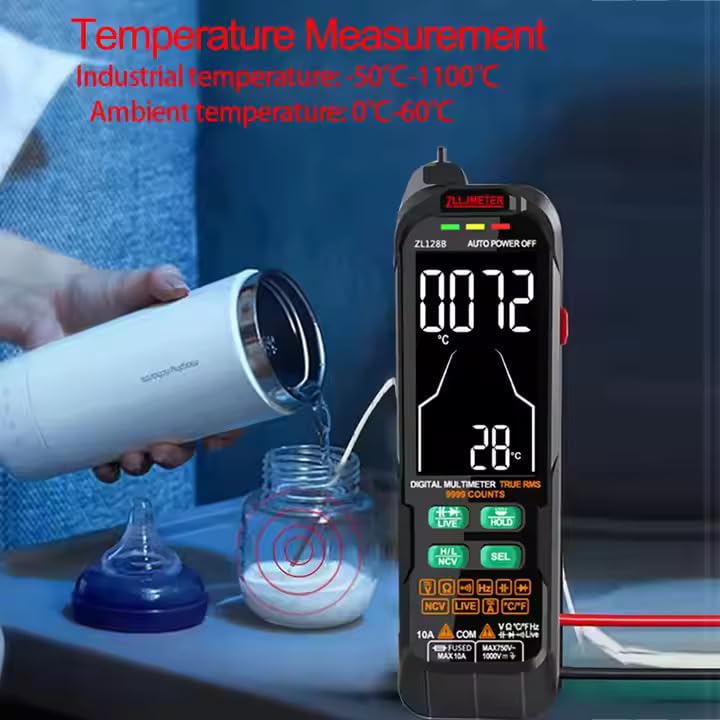
Figure 7: Measuring temperature using the included thermocouple probe.
5. Maintenance
5.1 Cleaning
Wipe the multimeter casing with a damp cloth and mild detergent. Do not use abrasives or solvents. Ensure the device is off and disconnected from any circuits before cleaning.
5.2 Battery Charging
Recharge the internal lithium battery when the low battery indicator appears on the display. Use only the provided USB cable or a compatible charger. Overcharging or using incompatible chargers may damage the battery.
5.3 Storage
When not in use for extended periods, store the multimeter in a cool, dry place, away from direct sunlight and extreme temperatures. It is recommended to fully charge the battery before long-term storage and to recharge it every few months to maintain battery health.
5.4 Test Lead Inspection
Regularly inspect the test leads for any signs of damage, such as cracked insulation, exposed wires, or loose connections. Replace damaged test leads immediately to ensure safety and accurate measurements.
6. Troubleshooting
- Multimeter does not power on:
- Ensure the battery is charged. Connect the USB cable and charge for at least 30 minutes.
- Check if the power button is pressed and held sufficiently.
- No reading or "OL" (Overload) displayed:
- Verify that the test leads are correctly inserted into the appropriate jacks for the selected function.
- Ensure the multimeter is in the correct measurement mode.
- Check if the circuit or component being measured is within the multimeter's range. "OL" often indicates a value exceeding the maximum range or an open circuit.
- For resistance/continuity, ensure the component is isolated from power.
- Inaccurate readings:
- Check battery level; low battery can affect accuracy.
- Ensure test leads are making good contact with the circuit.
- Verify the correct measurement mode is selected.
- Avoid strong electromagnetic interference.
- NCV or Live Wire detection not working:
- Ensure the NCV/LIVE function is activated.
- The sensor needs to be close to the AC voltage source.
7. Specifications
The following table provides detailed technical specifications for the ZLLJMETER ZL128B Digital Multimeter.

Figure 8: Technical specifications for ZL128B.
| Parameter | Specification |
|---|---|
| Display | 9999 Counts LCD with Backlight |
| DC Voltage (Auto Mode) | 0.5V ~ 1000V, Accuracy: ±(1.2%+3), Resolution: 1V |
| DC Voltage (Manual Mode) | 0.5V ~ 1000V, Accuracy: ±(1.2%+3), Resolution: 1V |
| AC Voltage (Auto Mode) | 1V ~ 750V, Accuracy: ±(1.2%+5), Resolution: 0.1V |
| AC Voltage (Manual Mode) | 0V ~ 750V, Accuracy: ±(1.2%+5), Resolution: 0.1V |
| DC Current | 0mA ~ 10A |
| AC Current | 0mA ~ 10A |
| Resistance | 0.1Ω ~ 100MΩ, Accuracy: ±(1.2%+5), Resolution: 0.01MΩ |
| Capacitance | 0 ~ 100mF, Accuracy: ±(4.0%+5), Resolution: 0.01mF |
| Frequency | 0 ~ 10MHz, Accuracy: ±(2%+5), Resolution: 0.01MHz |
| True RMS | Yes |
| Diode Test | Yes |
| On-off Beep (Continuity) | Yes |
| NCV Voltage Pen Detection | Yes |
| Live Wire Detection | Yes |
| Data Hold | Yes |
| Auto Power Off | Yes |
| Flashlight | Yes |
| Power Source | Rechargeable Lithium Battery (1000mAh) |
| Operating Voltage (Min) | 0.5 Volts |
| Safety Standard | IEC 61010-1 |
| Dimensions (L x W x H) | 16.5 x 8 x 2.5 cm |
| Weight | 300 g |
| Included Components | 1 Manual, 1 Meter, 1 USB Cable, 1 Test Lead, 1 Thermocouple |
8. Warranty and Support
8.1 Warranty Information
The ZLLJMETER ZL128B Digital Multimeter comes with a 1-Year Warranty from the date of purchase. This warranty covers manufacturing defects and malfunctions under normal use. It does not cover damage caused by misuse, accidents, unauthorized modifications, or improper operation.
Please retain your purchase receipt as proof of purchase for warranty claims.
8.2 Customer Support
For technical assistance, warranty claims, or any questions regarding the ZLLJMETER ZL128B, please contact the manufacturer or authorized distributor.
Manufacturer: Shenzhen Zhuoliang Laojiang Instrument Co., Ltd.
Importer/Packer (India): MDS Automech Solutions
- Address: Q-106, Phase 3, Shivalik Nagar, BHEL, Haridwar, Uttarakhand-249403, India
- Contact: +91-9870694636
- Email: mohit@mdsautomech.in
When contacting support, please have your product model (ZL128B) and purchase details ready.