ZLYMTXHW GIB161.1E
Air Damper Actuator GIB161.1E Instruction Manual
Model: GIB161.1E | Brand: ZLYMTXHW
1. Introduction
This manual provides comprehensive instructions for the installation, operation, and maintenance of the ZLYMTXHW GIB161.1E Air Damper Actuator. This device is designed for precise regulation and shut-off of dampers in ventilation and air conditioning plants. Please read this manual thoroughly before installation and operation to ensure safe and efficient use.
2. Safety Instructions
Always observe the following safety precautions to prevent personal injury and damage to the equipment:
- Installation and maintenance should only be performed by qualified personnel.
- Disconnect power before performing any work on the actuator or connected systems.
- Ensure proper grounding to prevent electrical shock.
- Do not operate the actuator beyond its specified voltage and torque limits.
- Protect the device from moisture and extreme temperatures unless otherwise specified.
3. Product Overview
The GIB161.1E Air Damper Actuator is a robust device engineered for reliable control of air dampers. It features a precise positioning signal input and operates on AC 24 V.
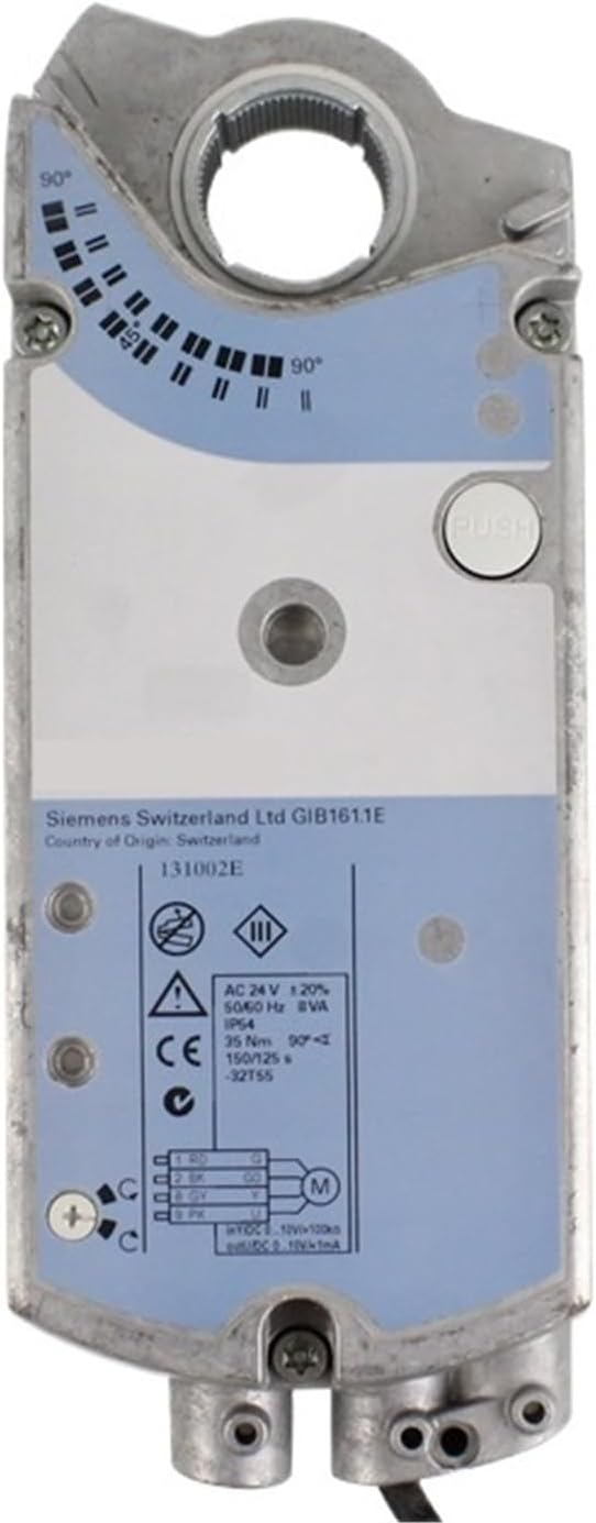
Figure 3.1: Front view of the GIB161.1E Air Damper Actuator. This image displays the main body of the actuator, including the visible Siemens Switzerland Ltd branding, the model number GIB161.1E, and a label detailing electrical specifications such as AC 24V operating voltage, IP54 protection, and positioning time. A push button for manual override is also visible.

Figure 3.2: Angled view of the GIB161.1E Air Damper Actuator. This perspective highlights the side of the actuator where electrical connections are made, showing the cable entry points and the overall compact design. The angular position indicator is also visible.
4. Technical Specifications
The following table details the key technical specifications for the GIB161.1E Air Damper Actuator:
| Parameter | Value |
|---|---|
| Model Number | GIB161.1E |
| Torque | 35 Nm |
| Air Damper Area | 6 m² |
| Positioning Time | 150 s |
| Positioning Signal | DC 0...10 V |
| Operating Voltage | AC 24 V |
| Item Weight | 1.76 ounces |
| Package Dimensions | 11.81 x 7.87 x 3.94 inches |
5. Installation and Setup
Proper installation is crucial for the optimal performance of the GIB161.1E actuator. Follow these steps carefully:
- Mounting the Actuator: Securely attach the actuator to the damper shaft using appropriate mounting hardware. Ensure the actuator is aligned correctly with the damper's rotation axis.
- Electrical Connections: Refer to the wiring diagram on the actuator's label for correct electrical connections. Connect the AC 24 V power supply and the DC 0...10 V positioning signal wires to the designated terminals. Ensure all connections are tight and insulated.
- Initial Position Setting: Manually adjust the damper to its desired initial position if required. The actuator may have a manual override button (visible in Figure 3.1) for this purpose.
- Power On: Once all connections are verified, apply power to the actuator.

Figure 5.1: Wiring Diagram and Technical Label. This image provides a detailed view of the electrical specifications and connection points printed on the actuator's housing, essential for correct wiring during installation.
6. Operation
The GIB161.1E actuator operates based on the incoming DC 0...10 V positioning signal. The actuator will move the damper to a position corresponding to the signal voltage.
- A 0 V signal typically corresponds to one extreme position (e.g., fully closed).
- A 10 V signal typically corresponds to the other extreme position (e.g., fully open).
- Intermediate voltages (e.g., 5 V) will position the damper proportionally (e.g., 50% open).
Observe the position indicator on the actuator to confirm the damper's current angle.

Figure 6.1: Actuator with Angular Position Indicator. This image shows the top surface of the actuator, clearly displaying the marked scale (0° to 90°) and the indicator that shows the current rotational position of the damper.
7. Maintenance
The GIB161.1E Air Damper Actuator is designed for minimal maintenance. However, periodic checks are recommended to ensure long-term reliability:
- Visual Inspection: Periodically inspect the actuator for any signs of physical damage, loose connections, or excessive dust accumulation.
- Cleaning: If necessary, gently clean the exterior of the actuator with a dry, soft cloth. Do not use abrasive cleaners or solvents.
- Connection Check: Ensure all electrical connections remain secure.
- Damper Movement: Verify that the damper moves freely and without obstruction.
Warning:
Do not attempt to disassemble the actuator. There are no user-serviceable parts inside. Disassembly will void any warranty.
8. Troubleshooting
If the GIB161.1E actuator is not functioning as expected, refer to the following troubleshooting guide:
| Problem | Possible Cause | Solution |
|---|---|---|
| Actuator does not move | No power supply; Incorrect wiring; Faulty signal; Damper obstructed | Check AC 24 V power supply; Verify wiring against diagram; Check DC 0...10 V signal source; Clear any obstructions from damper movement. |
| Actuator moves erratically | Unstable power supply; Noisy signal; Loose connections | Ensure stable power; Check signal quality; Tighten all electrical connections. | `
| Actuator does not reach full travel | Incorrect signal range; Mechanical obstruction; Actuator fault | Verify signal range (0-10V); Check for physical obstructions; If problem persists, contact support. |
If the issue cannot be resolved using this guide, please contact ZLYMTXHW customer support.
9. Warranty Information
This product is covered by a standard manufacturer's warranty. Please refer to the warranty card included with your purchase or visit the official ZLYMTXHW website for detailed terms and conditions. The warranty typically covers defects in materials and workmanship under normal use.
Note:
Damage resulting from improper installation, misuse, unauthorized modifications, or failure to follow the instructions in this manual will void the warranty.
10. Customer Support
For technical assistance, spare parts, or warranty claims, please contact ZLYMTXHW customer support through the following channels:
- Website: Visit ZLYMTXHW on Amazon (for general product information)
- Email: Refer to your product packaging or purchase documentation for direct support email.
- Phone: Refer to your product packaging or purchase documentation for direct support phone number.
When contacting support, please have your product model number (GIB161.1E) and purchase date available.
Ask a question about this manual
Ask about setup, troubleshooting, compatibility, parts, safety, or missing instructions. Manuals+ will review the question and use this page’s manual context to help answer it.