
1. Introduction
The Anjfylque Hybrid Solar Inverter is an advanced all-in-one solution designed for both off-grid and on-grid solar power systems. This 3.6KW, 48VDC-120AC pure sine wave inverter integrates a 40A battery charger and an 80A MPPT solar charge controller (Max 300VDC). It supports split-phase (120V/240V) and single-phase (120V) output, offering versatile energy management. Equipped with built-in WiFi, it allows for real-time monitoring via a mobile application, providing comprehensive control over your solar power system. This manual provides essential information for safe installation, operation, and maintenance of your inverter.
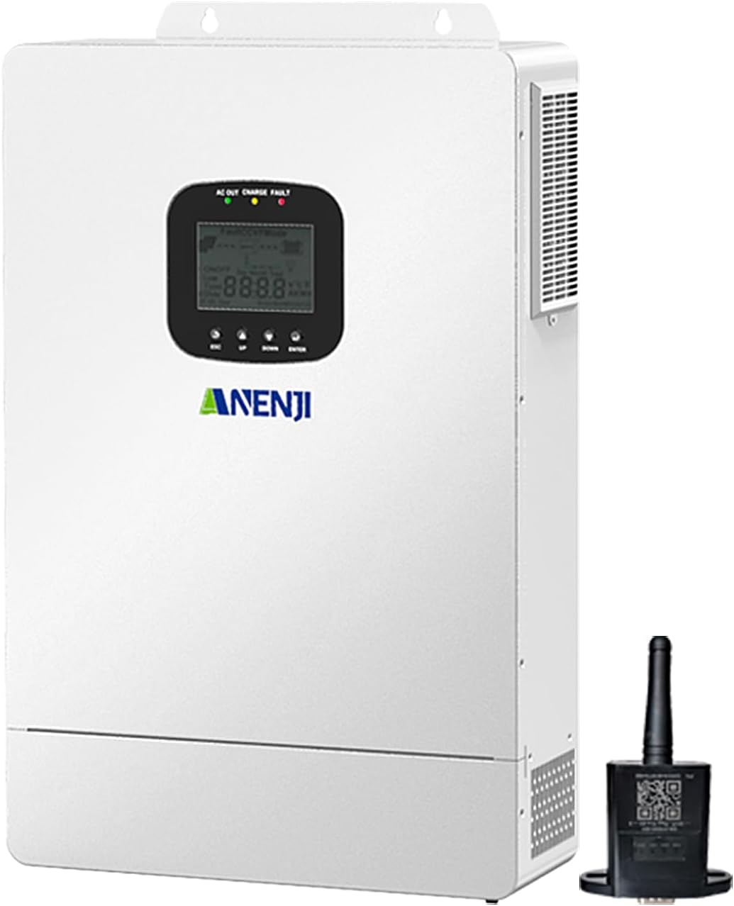
Figure 1.1: Front view of the Anjfylque Hybrid Solar Inverter, showcasing its compact design and integrated display.
2. Safety Information
Please read all instructions and warnings carefully before installation and operation. Failure to follow these instructions may result in electric shock, fire, severe injury, or death. Keep this manual for future reference.
- Qualified Personnel: Installation and maintenance must be performed by qualified personnel with knowledge of electrical systems and safety regulations.
- High Voltage: The inverter operates at high voltages. Do not open the unit or attempt repairs unless specifically instructed by the manufacturer.
- Grounding: Ensure the inverter is properly grounded to prevent electric shock.
- Battery Safety: Batteries can produce explosive gases. Ensure adequate ventilation and avoid sparks or flames near batteries. Wear appropriate personal protective equipment (PPE).
- Ventilation: Install the inverter in a well-ventilated area to prevent overheating. Maintain clear space around the unit for airflow.
- Overload Protection: The inverter has built-in overload protection. Do not exceed the rated power capacity.
- Emergency Shutdown: Familiarize yourself with the emergency shutdown procedures for the entire solar system.

Figure 2.1: The inverter incorporates an 8-way protection hub, including short circuit cutoff, arc fault detection, overcurrent relay, thermal shutdown, rectifier locked, overload shutoff, voltage overload, and charge guardian for enhanced safety and durability.
3. Product Overview
3.1 Key Features
- All-in-One Design: Integrates inverter, battery charger, and MPPT solar charge controller.
- Pure Sine Wave Output: Ensures stable and clean power for sensitive electronics.
- Parallel Capability: Expandable up to 21.6KW with 6-unit parallel connection for increased power output.
- Flexible Output: Supports 120V single-phase, 120V/240V split-phase, or 208V 3-phase configurations.
- WiFi Monitoring: Real-time system monitoring via a dedicated mobile application.
- Multiple Charging & Output Modes: Adaptable energy management for various scenarios.
- Time Slot Charging & Discharging: Optimizes energy usage based on electricity tariffs.
- Versatile Battery Compatibility: Compatible with 48V AGM/Gel/Flooded/Lithium batteries, with battery-free operation support.
3.2 Package Contents
Verify that all items listed below are included in your package:
- Hybrid Solar Inverter Unit (x1)
- Current sharing detection line (x1)
- Anti-reverse current CT (x1)
- WiFi Module (x1)
- Installation Toolkit (x1)
- Instruction Manual (x1)

Figure 3.1: Contents included with the Anjfylque Hybrid Solar Inverter.
3.3 Inverter Ports Overview
Familiarize yourself with the various ports and indicators on your inverter for proper connection and operation.

Figure 3.2: Detailed breakdown of the inverter's interface, including indicator light, LCD screen, touch keys, overload protector, grounding screw hold, AC output port, WiFi port, AC input port, RS485-2/RS485-1 communication ports, USB communication port, ON/OFF rocker switch, cooling fan, dry contact port, current sharing port, parallel communication port, battery port, and PV port.
4. Setup and Installation
Proper installation is crucial for the inverter's performance and safety. Ensure all local electrical codes and regulations are followed.
4.1 Mounting the Inverter
- Choose a vertical, non-flammable surface.
- Ensure adequate clearance (at least 20 cm) around the inverter for proper ventilation.
- Mount the inverter securely using the provided installation toolkit.
4.2 Wiring Connections
All wiring must be done with the inverter and all power sources (solar panels, batteries, AC grid) disconnected and de-energized. Use appropriate wire gauges as specified in the detailed wiring diagram.

Figure 4.1: Comprehensive wiring diagram for the hybrid inverter system, illustrating connections for solar panels (PV input), AC input from grid/generator, AC output to home loads, and battery bank. Recommended cable gauges and breaker sizes are indicated.
- Battery Connection: Connect the 48V battery bank to the inverter's battery terminals. Ensure correct polarity. The inverter is compatible with AGM/Gel/Flooded/Lithium batteries.
- PV Input Connection: Connect your solar panel array to the PV input terminals. Ensure the PV open circuit voltage (Voc) does not exceed 300VDC. Recommended configuration is series connection.
- AC Input Connection: Connect the AC grid or generator input to the AC input terminals.
- AC Output Connection: Connect your home loads to the AC output terminals. The rated output is 3600W, 110V/120V.
- Grounding: Connect the inverter's grounding terminal to a reliable earth ground.
4.3 WiFi Module Setup
The included WiFi module enables remote monitoring of your inverter system via a mobile application. Follow the instructions provided with the WiFi module for registration and setup. This typically involves connecting the module to the inverter's WiFi port and configuring it through the app.

Figure 4.2: The WiFi module allows for convenient remote monitoring of your inverter's status and performance from your mobile device.
5. Operating Modes
The inverter offers flexible charging and output modes to optimize energy management based on your preferences and system requirements.
5.1 Charger Source Priority
This setting determines how the battery bank is charged from different power sources.

Figure 5.1: Options for prioritizing charging sources for the battery bank.
- Solar First AC Input Next: Prioritizes solar power for charging. AC input charges only when solar power is unavailable.
- Solar and AC Input Simultaneously: Charges the battery from both solar and AC power concurrently.
- Solar Only: The inverter charges the battery exclusively from available solar power.
- Utility Priority (Hybrid): Prioritizes utility power for charging, using solar as a secondary source.
5.2 Output Source Priority
This setting controls how your appliances are powered to avoid interruptions.

Figure 5.2: Options for prioritizing power sources for connected loads.
- Solar First: The inverter uses solar power to supply loads first. If solar input is insufficient, it compensates with AC input.
- AC First: The inverter prioritizes AC input for all loads. DC sources (solar/battery) are used only when AC power is unavailable.
- DC Priority: Prioritizes solar power first. If solar is not enough, the battery bank will supply power. AC input only powers loads when a low-battery warning is triggered.
- Inverter Priority: Prioritizes battery power, using AC input only when battery voltage is low.
5.3 Time Slot Charging & Discharging Function
This feature allows you to schedule charging and discharging times, which is ideal for maximizing PV energy utilization and reducing utility costs in regions with peak/valley electricity tariffs. Refer to the inverter's display or mobile app for configuration options.
6. Parallel Operation
The Anjfylque Hybrid Solar Inverter supports parallel connection of up to 6 units, allowing for scalable power solutions for larger residential or commercial applications. This enables configurations for single-phase, split-phase, or 3-phase systems.
6.1 Split-Phase Connection (120V/240V)
For 240V and 120V systems, typically used in residential applications.

Figure 6.1: Split-Phase connection with one inverter per phase (P1 and P2).

Figure 6.2: Split-Phase connection with two inverters per phase (P1 and P2).

Figure 6.3: Split-Phase connection with up to six inverters in two groups of three parallel units.
6.2 3-Phase Connection (208V)
For commercial applications requiring 208V systems.

Figure 6.4: 3-Phase connection with one inverter in each phase (P1, P2, P3).

Figure 6.5: 3-Phase connection with five inverters, showing configurations for uneven load distribution across phases.

Figure 6.6: 3-Phase connection with a maximum of six inverters, suitable for 208V commercial systems that may also require 240V or 120V systems.
7. Maintenance
Regular maintenance ensures optimal performance and longevity of your inverter.
- Cleaning: Keep the inverter's exterior clean and free of dust. Ensure ventilation openings are not blocked. Use a dry cloth for cleaning.
- Connection Checks: Periodically inspect all electrical connections (PV, battery, AC input/output) for tightness and signs of corrosion. Tighten any loose connections.
- Ventilation: Ensure the installation area remains well-ventilated and free from obstructions.
- Battery Health: Monitor battery voltage and health according to battery manufacturer guidelines.
- Firmware Updates: Check for any available firmware updates via the mobile app or manufacturer's website to ensure optimal performance and new features.
8. Troubleshooting
This section provides guidance on common issues you might encounter. For complex problems, contact qualified technical support.
| Problem | Possible Cause | Solution |
|---|---|---|
| Inverter not turning on | No battery connection, low battery voltage, DC breaker off, faulty wiring. | Check battery connections and voltage. Ensure DC breaker is ON. Verify wiring. |
| No AC output | Overload, short circuit, AC breaker tripped, inverter fault. | Reduce load. Check for short circuits. Reset AC breaker. Check inverter display for error codes. |
| Low PV charging power | Shaded panels, dirty panels, incorrect PV wiring, MPPT fault. | Clear shading/clean panels. Verify PV wiring and voltage. |
| WiFi monitoring not working | WiFi module not connected, network issues, app configuration error. | Ensure WiFi module is securely connected. Check local network connectivity. Reconfigure app settings. |
| Unusual noises | Loose components, fan obstruction, internal fault. | Check for loose parts. Ensure cooling fan is clear. If noise persists, contact support. |
9. Specifications
| Feature | Specification |
|---|---|
| Model Name | ANJ-3600W-LVP-WIFI |
| Wattage | 3600 watts |
| Power Source | Solar and Battery Powered |
| Recommended Uses | Home, Outdoor Installations |
| Brand | Anjfylque |
| Product Dimensions | 15 x 11 x 3.9 inches |
| Item Weight | 17.6 pounds |
| MPPT Charger | 80A (Max 300VDC) |
| Battery Charger | 40A |
| Parallel Support | Up to 6 units (21.6KW) |
| Output Voltage | 120V AC (Single-phase), 120V/240V (Split-phase), 208V (3-phase) |
| Battery Compatibility | 48V AGM/Gel/Flooded/Lithium |
10. Warranty and Support
For warranty information and technical support, please refer to the documentation provided with your purchase or contact the seller directly. Ensure you have your product model number and purchase details ready when seeking assistance.