1. Introduction
Thank you for choosing the ORTEC Solar 48V 5.6Kw/5600Va MPPT Wi-Fi Full Sine Wave Smart Inverter. This manual provides essential information for the safe installation, operation, and maintenance of your inverter. Please read this manual thoroughly before installation and operation to ensure optimal performance and safety.
1.1 Important Safety Instructions
- Read all instructions and cautionary markings on the unit and in this manual before installation.
- Only qualified personnel should install and service this device.
- Before connecting to the power source, ensure all connections are correct and secure.
- Do not disassemble the inverter. There are no user-serviceable parts inside.
- Ensure proper ventilation around the inverter to prevent overheating.
- Keep children away from the inverter.
2. Product Overview
The ORTEC Solar Smart Inverter is a multi-functional inverter/charger, combining functions of an inverter, MPPT solar charger, and battery charger to offer uninterruptible power support in a portable size. Its comprehensive LCD display offers user-configurable and easy-accessible button operation such as battery charging current, AC/solar charger priority, and acceptable input voltage based on different applications.
2.1 General Features
- 100% Compatibility with Lithium Batteries.
- 450 VDC Panel Connection capability.
- Integrated 120A MPPT Charge Control System.
- Built-in Wi-Fi Communication for remote monitoring.
- 4.3-inch Wide Color Touch Screen for intuitive control.
- Battery-less Operation Capability.
2.2 Component Identification
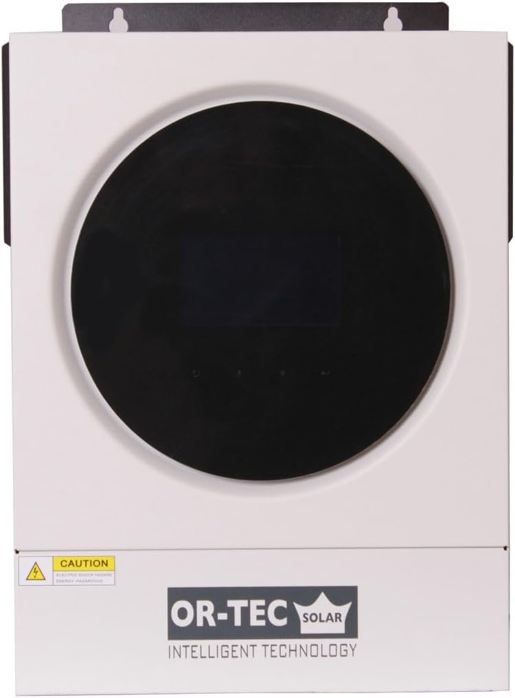
Figure 2.2.1: Front view of the ORTEC Solar Inverter, showing the central display and OR-TEC SOLAR branding.

Figure 2.2.2: Front-right view of the inverter, highlighting the side ventilation and power switch.

Figure 2.2.3: Front-left view of the inverter, showing the left side ventilation.

Figure 2.2.4: Rear view of the inverter, detailing AC input/output, PV input, battery terminals, and communication ports.
3. Setup and Installation
3.1 Mounting the Inverter
The inverter is designed for wall mounting. Choose a suitable location that is dry, well-ventilated, and protected from direct sunlight and moisture. Ensure sufficient clearance around the unit for proper airflow.
- Mark the positions for the mounting screws on the wall using the inverter's mounting bracket as a template.
- Drill appropriate holes and insert wall anchors if necessary.
- Securely mount the inverter to the wall.
3.2 System Connection Diagram
The following diagram illustrates a typical connection setup for the ORTEC Solar Inverter, integrating solar panels, grid power, a generator, and a battery bank to supply power for home use.

Figure 3.2.1: Diagram showing the connection of solar panels, grid, generator, battery, and household loads to the inverter.
3.3 Wiring Connections
All wiring must comply with local electrical codes and regulations. Use appropriate cable sizes for all connections.
- PV Input: Connect solar panel strings to the PV+ and PV- terminals. Ensure the total open circuit voltage does not exceed 450 VDC.
- Battery Connection: Connect the battery bank to the battery terminals. Observe correct polarity (positive to positive, negative to negative).
- AC Input: Connect the grid power or generator output to the AC Input terminals.
- AC Output: Connect your household loads or distribution panel to the AC Output terminals.
- Communication Ports: Utilize the USB, RS232/RS485, Wi-Fi, or Dry-Contact ports for monitoring and communication as required.
Caution: Ensure all power sources are disconnected before making any wiring connections to prevent electric shock.
4. Operating Instructions
4.1 Powering On/Off
- To Power On: Ensure all connections are secure. Turn on the battery breaker first, then the AC input breaker (if connected), and finally the PV input breaker. Press the power button on the inverter.
- To Power Off: Turn off the PV input breaker first, then the AC input breaker, and finally the battery breaker. Press and hold the power button on the inverter until it shuts down.
4.2 Display and Settings
The 4.3-inch color touch screen provides real-time system status and allows for configuration of various parameters. Navigate through the menus using the touch interface to view information such as input/output voltage, current, power, battery status, and operational modes.
- Monitoring: View current system status, energy production, and consumption.
- Settings: Adjust battery charging current, AC/solar charger priority, output voltage range, and other operational parameters. Refer to the detailed on-screen menu for specific options.
- Wi-Fi Communication: Configure Wi-Fi settings through the display to connect the inverter to your local network for remote monitoring via a dedicated application (if available).
5. Maintenance
Regular maintenance ensures the longevity and optimal performance of your ORTEC Solar Inverter.
5.1 Routine Checks
- Monthly: Inspect the inverter for any visible damage, loose connections, or unusual noises. Check ventilation openings for dust accumulation.
- Quarterly: Verify that all cables are securely connected and free from corrosion. Check battery terminals for cleanliness and tightness.
- Annually: Have a qualified technician perform a thorough inspection of the entire system, including voltage and current measurements.
5.2 Cleaning
Clean the exterior of the inverter with a soft, dry cloth. Do not use liquid cleaners or solvents. Ensure ventilation openings are clear of dust and debris to maintain proper cooling.
6. Troubleshooting
This section provides solutions to common issues you might encounter with your inverter. If the problem persists, contact customer support.
6.1 Common Issues and Solutions
- Inverter not powering on: Check battery connections, battery voltage, and all circuit breakers (battery, AC input, PV input). Ensure the power button is pressed correctly.
- No AC output: Verify AC output breaker, check for overload conditions, and ensure the inverter is not in fault mode. Check battery charge level.
- Low battery charge: Inspect solar panel connections, ensure panels are clean and receiving sunlight. Check MPPT charger settings and battery health.
- Overload warning: Reduce the connected load. The inverter may temporarily shut down to protect itself.
- Unusual noises or smells: Immediately power off the inverter and disconnect all power sources. Contact customer support.
7. Technical Specifications
The following table details the technical specifications for the ORTEC Solar Inverter Model VM-5.6.
| Category | Parameter | Value |
|---|---|---|
| Model | Model Name | VM-5.6 |
| Operating Power | 5600VA/5600W | |
| AC Input | Voltage | 230 VAC |
| Adjustable Voltage | 170-280 VAC (for Electronic Products) / 90-280 VAC (for Home Applications) | |
| Frequency Range | 50 Hz/60 Hz (Automatic Settings) | |
| AC Output | AC Output Voltage | 230 VAC ±5% |
| Instantaneous Peak Power | 11200VA | |
| Efficiency | 93% | |
| Sine Wave Type | Full Sine Wave | |
| Battery | Battery Voltage | 48 VDC |
| High Charge Protection | 63 VDC | |
| Solar Charge Control & Grid Charge | Solar Charge Control Type | MPPT |
| Maximum PV Voltage | 450 VDC | |
| Open Circuit Voltage | 6000 W | |
| Maximum PV Power | 6000 W | |
| MPPT Operating Voltage Range | 120-450 VDC | |
| Maximum Solar Charge Current | 120 A | |
| Maximum Grid Charge Current | 100 A | |
| Total Charge Current | Maximum Charge Current | 120 A |
| Physical | Dimensions (W x H x D) | 119 x 313 x 423 mm |
| Net Weight | 12.00 kg | |
| Interface Connection | USB/RS232/RS485/Wi-Fi/Dry-Contact | |
| Environmental Factors | Ambient Humidity Level | 5% to 95% Relative Humidity (Non-condensing) |
| Operating Temperature | -10°C to 50°C | |
| Storage Temperature | -15°C to 60°C |
8. Warranty and Support
For warranty information and technical support, please refer to the documentation provided at the time of purchase or contact your authorized ORTEC dealer. Ensure you have your product model number (ORM5.6KW) and purchase details available when seeking support.