1. Introduction
This instruction manual provides detailed guidance for the UCVJXDEM Universal EDP LCD Driver Board, specifically the 1366x768 resolution model. This adapter board is designed to convert HDMI signals to EDP for various LCD panels ranging from 10 to 17 inches. It is intended for users with technical knowledge in electronics and display systems. Please read this manual thoroughly before installation and operation to ensure correct usage and optimal performance.
2. Product Overview
The UCVJXDEM EDP LCD Driver Board is a versatile component for display projects, offering resolution adaptation, image quality optimization, and multi-system compatibility. It features various interfaces for external devices and is designed with compact dimensions for integration into various display enclosures.
2.1 Board Components

Figure 1: Top view of the UCVJXDEM Universal EDP LCD Driver Board. This image displays the main components including the central processing chip, various capacitors, resistors, and connectors for power, video input, and panel output.
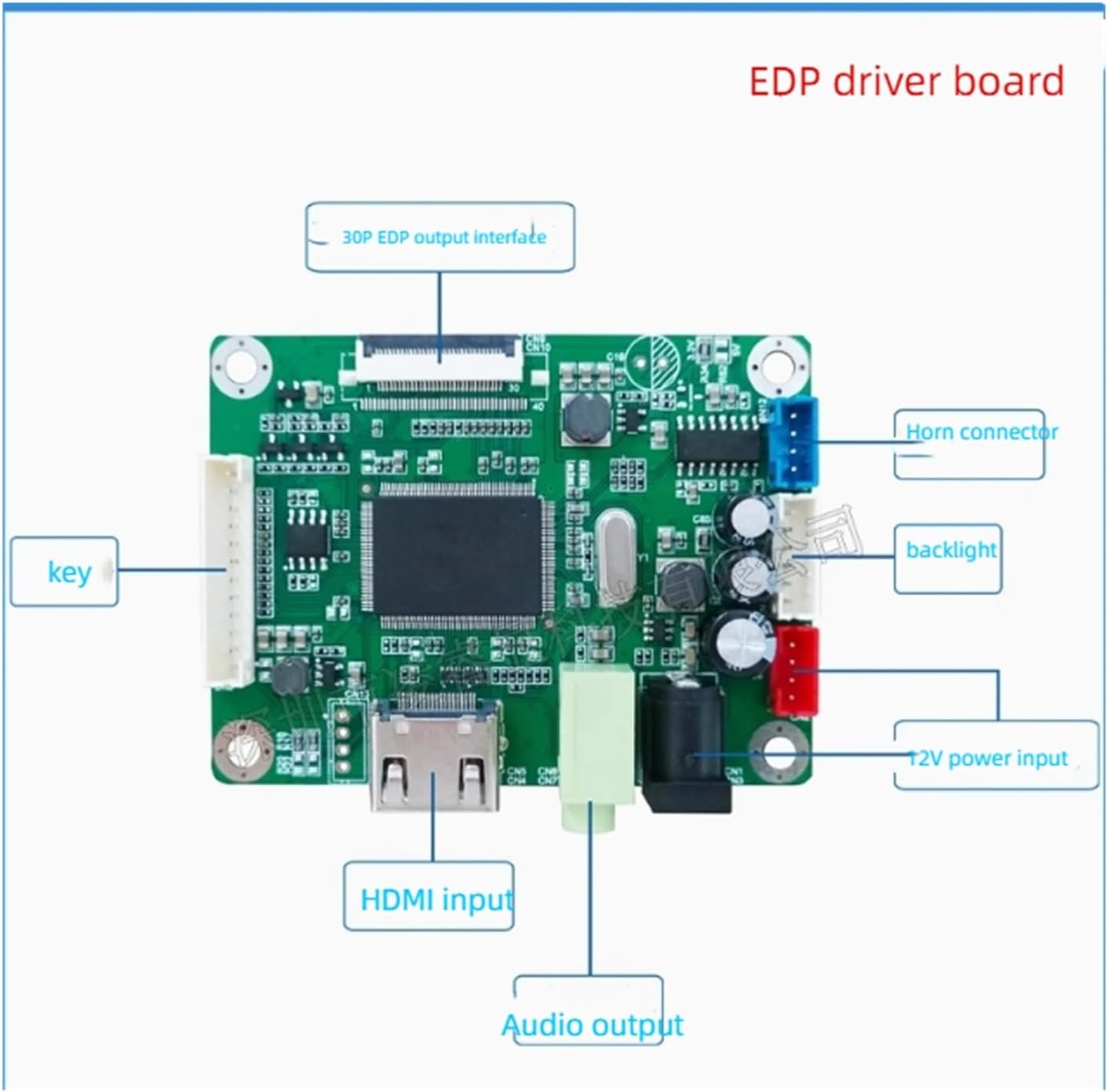
Figure 2: Labeled diagram of the EDP driver board interfaces. Key interfaces include the 30P EDP output interface, Horn connector, Backlight connector, 12V power input, HDMI input, Audio output, and Key connector for control buttons.

Figure 3: Dimensional drawing of the EDP driver board. This diagram provides the overall dimensions of the board in millimeters, indicating key measurements such as 72.00mm length, 56.00mm width, and various mounting hole positions.

Figure 4: Back view of the EDP driver board. This image shows the reverse side of the board, highlighting important identifiers such as LRX_H2EDP556_V1.0, A00363-Y648-291122, and DLL040490. It also indicates the DC-IN, HDMI, and Earphone ports from this perspective.
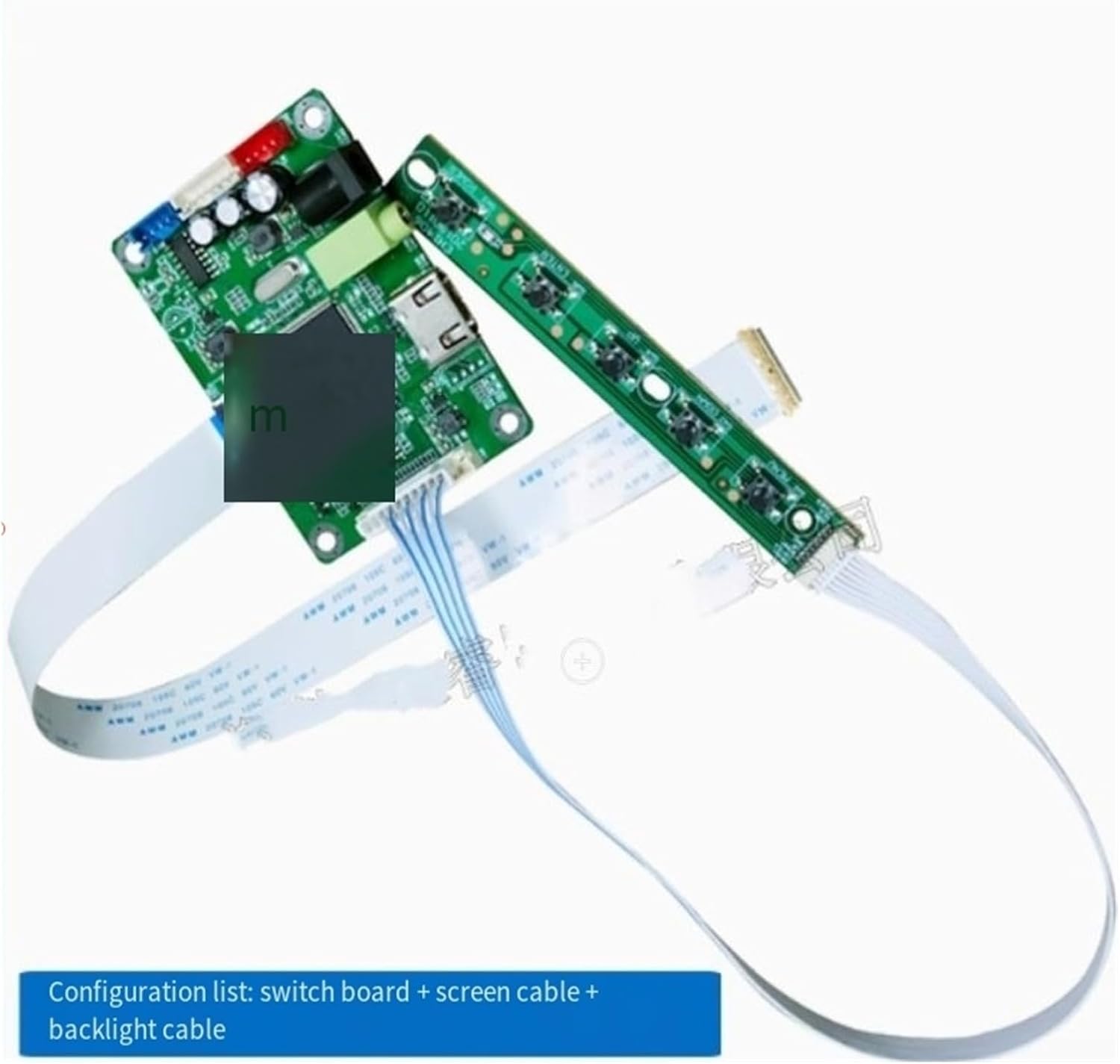
Figure 5: Configuration list. This image illustrates the typical components included with the driver board: the main driver board, a separate switch board for controls, a screen cable (EDP cable), and a backlight cable.
3. Setup Instructions
Before beginning installation, ensure all power is disconnected from your display panel and the driver board. It is highly recommended to consult customer service or verify the complete screen model clearly before connecting to ensure compatibility.
- Prepare Components: Unpack the EDP driver board, switch board, screen cable, and backlight cable.
- Connect EDP Panel: Carefully connect the screen cable (EDP cable) to the 30P EDP output interface on the driver board and to the corresponding input on your EDP LCD panel. Ensure correct orientation and secure connection.
- Connect Backlight: Attach the backlight cable from your LCD panel to the 'backlight' connector on the driver board (refer to Figure 2).
- Connect Control Buttons: Connect the switch board to the 'key' connector on the driver board. This board typically provides power, menu, and input selection controls.
- Connect HDMI Source: Connect your HDMI input device (e.g., computer, media player) to the 'HDMI input' port on the driver board.
- Connect Audio Output (Optional): If external audio is desired, connect speakers or headphones to the 'Audio output' port.
- Apply Power: Connect a 12V DC power supply to the '12V power input' port on the driver board. Ensure the power supply meets the board's specifications.
- Initial Power On: Power on the display panel and then the driver board. The display should show the input from the HDMI source.
4. Operating Instructions
Once the driver board is correctly installed and powered, operation is straightforward.
- Power On/Off: Use the power button on the connected switch board to turn the display on or off.
- Input Selection: If multiple inputs are supported (e.g., via the switch board), use the designated buttons to cycle through available video sources.
- Resolution Adaptation: The board supports various resolutions, automatically adapting to the connected EDP panel and HDMI input. It optimizes image quality, enhancing color, contrast, and detail.
- Menu Navigation: If the switch board includes menu buttons, you can access and adjust display settings such as brightness, contrast, and color balance. Refer to the specific switch board's documentation for detailed menu options.
5. Maintenance
Proper maintenance ensures the longevity and reliable performance of your EDP LCD Driver Board.
- Cleaning: Keep the board free from dust and debris. Use a soft, dry cloth or compressed air for cleaning. Avoid liquid cleaners.
- Environment: Operate the board in a dry, well-ventilated environment. Avoid exposure to extreme temperatures, humidity, or direct sunlight.
- Connections: Periodically check all cable connections to ensure they are secure and free from damage.
- Power Management: The board is designed for energy efficiency with low power consumption when idle. Disconnect power when the display system will not be used for extended periods.
6. Troubleshooting
If you encounter issues with your EDP LCD Driver Board, refer to the following troubleshooting steps:
- No Display:
- Ensure the 12V power supply is correctly connected and functioning.
- Verify that the screen cable (EDP) is securely connected to both the driver board and the LCD panel.
- Check if the HDMI source is active and outputting a signal.
- Confirm the LCD panel is compatible with the driver board's output specifications (e.g., 1366x768 resolution).
- Incorrect Resolution or Distorted Image:
- Ensure the HDMI source is set to an output resolution compatible with the EDP panel and driver board.
- Restart the system (power off and on) to allow the board to re-detect the panel.
- No Audio:
- Verify that the audio output cable is correctly connected to external speakers or headphones.
- Check the audio settings on your HDMI source device.
- Buttons Not Responding:
- Ensure the switch board is properly connected to the 'key' connector on the driver board.
- Inspect the switch board and cable for any visible damage.
If problems persist after following these steps, please contact customer service for further assistance.
7. Specifications
| Feature | Specification |
|---|---|
| Brand Name | UCVJXDEM |
| Model Number | wymlsh |
| Supported Resolution | 1366x768 (This variant) |
| Input Interface | HDMI |
| Output Interface | EDP (30-pin) |
| Supported Panel Size | 10 Inch to 17 Inch |
| Item Weight | 1.76 ounces |
| Package Dimensions | 0.39 x 0.39 x 0.39 inches |
| ASIN | B0FB8YN4XM |
| Part Numbers/Identifiers | LRX_H2EDP556_V1.0, A00363-Y648-291122, DLL040490 |
8. Warranty and Support
Warranty information for this product is typically provided by the seller at the time of purchase. Please retain your proof of purchase for any warranty claims. For technical support, troubleshooting assistance beyond this manual, or inquiries regarding specific screen model compatibility, please contact the seller or manufacturer's customer service directly. They can provide product-specific guidance and solutions.