1. Introduction
This manual provides comprehensive instructions for the installation, operation, and maintenance of your maXpeedingrods On Board Air Compressor System. This single-path system is designed to distribute air pressure equally to air springs, enhancing ride comfort and stability for trucks and vans. Please read this manual thoroughly before installation and use to ensure safe and efficient operation.
2. Safety Information
- Always wear appropriate personal protective equipment (PPE) during installation and maintenance.
- Ensure the vehicle is parked on a level surface and the engine is off before beginning any work.
- Disconnect the vehicle's battery before performing any electrical connections.
- Do not exceed the maximum operating pressure of 120 PSI. The recommended working pressure is 5-70 PSI.
- Verify all air line connections are secure and leak-free to prevent system failure.
- Keep hands and clothing clear of moving parts during operation.
- Ensure proper ventilation when working in enclosed spaces.
- Consult a qualified professional if you are unsure about any installation or maintenance steps.
3. Package Contents
Verify all items are present before beginning installation:
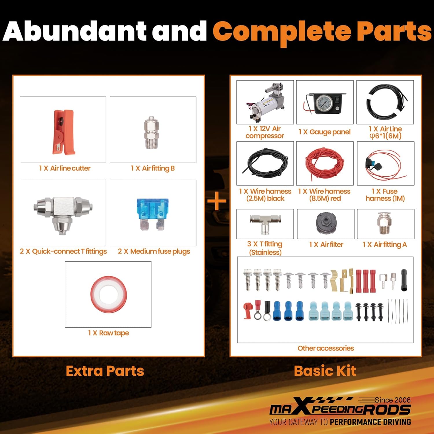
Image: Overview of the complete maXpeedingrods On Board Air Compressor Kit components, including the compressor, gauge panel, air lines, and various fittings and accessories.
- 1 x 12V Air Compressor
- 1 x Gauge Panel with Analog Gauge
- 1 x Air Line (6M / 19.68 ft)
- 1 x Wire Harness (2.5M) Black
- 1 x Wire Harness (8.5M) Red
- 1 x Fuse Harness (1M)
- 3 x T Fittings (Stainless)
- 1 x Air Filter
- 1 x Air Fitting A
- 1 x Air Fitting B
- 1 x Air Line Cutter
- 2 x Quick-connect T fittings
- 2 x Medium Fuse Plugs
- 1 x Raw Tape (Teflon Tape)
- Other accessories (mounting hardware, zip ties, wire connectors)
4. Specifications
- Brand:
- maXpeedingrods
- Style:
- Portable, Electric, Automotive, Single-Stage
- Max Air Pressure:
- Up to 120 PSI
- Recommended Working Pressure:
- 5-70 PSI
- Compressor Voltage:
- 12V
- Material:
- Aluminum Alloy (high-strength, corrosion-resistant), Zinc-Plated Carbon Steel (heavy duty, rust-resistant)
- Compatibility:
- Works with most air spring brands (5000 lbs or 7500 lbs air springs), fits most 1/2 Ton, 3/4 Ton, 1 Ton pickup trucks equipped with air bags suspension.

Image: Detailed dimensions of the air compressor unit and the analog gauge panel for installation planning.
5. Setup and Installation
This section guides you through the installation process. For a visual guide, please refer to the installation video below.
Video: Detailed installation guide for the maXpeedingrods Onboard Air Compressor Kit, demonstrating each step from unboxing to final setup.
5.1. Pre-Installation Steps
- Prepare the Compressor: Apply Teflon tape to the threaded area of the chosen air outlet fitting (threaded fitting recommended for better seal) and securely install it onto the compressor. Ensure the air outlet is not blocked.
- Install Intake Extension Fitting: Remove the plug from the compressor's intake port. Install the intake extension fitting and tighten it with a 10mm wrench.
- Modify Compressor Power Connector: Untangle the wiring harness. Cut off the wire connector from the power lead and use a wire stripper to remove insulation. Install the included red wire connector onto the wire and secure it with crimping pliers.
- Install Power Supply Wire to Switch: Locate the red wire on the pressure gauge. Install a wire connector. Insert the wire from the inline fuse into the connector and secure with crimping pliers. Connect this wire connector to the control switch.
- Extend Ground Point (if necessary): If the vehicle's ground point is far, install a negative wire to extend it. Otherwise, directly install to the original negative terminal. Use wire strippers to remove insulation, install the black terminal, and secure with crimping pliers.
- Install T-Connector: Remove the nut from the air line fitting. Slide the nut onto the air line with the flared end facing outward. Install the air line onto the fitting and push it fully into place. Tighten the nut with a 10mm wrench.
5.2. Mounting the Compressor
- Drill Mounting Holes: Lift the vehicle. Using a 3mm drill bit, drill four holes on the side of the frame as mounting points for the compressor.
- Mount the Compressor: Position the compressor's intake port facing towards the front of the vehicle. Use self-tapping screws to mount it to the frame. Install and tighten all screws using an 8mm deep socket.
- Attach Ground Wire: Attach the compressor's ground wire to one of the compressor mounting bolts and tighten the bolt.
5.3. Air Line Connections

Image: Illustration of quick connect air line fittings and tee fittings, highlighting the importance of proper installation for a tight, anti-leak seal.
- Install Rear Air Spring T-Connector: Cut a section of the hose to install the rear air spring. Use the air line cutter to cut off a section of air line. Remove the retaining nut, slide it onto the air line, and then install the air line onto the T-connector. Push it fully into place and install the nut. Use an 11mm wrench and a 10mm wrench to tighten.
- Install Air Lines for Rear Air Springs: These are the rear air spring lines. To install them onto the T-connector, remove the nut and put it in the air line. Install the air line, put the nut back on, and repeat for the other side. Use an 11mm wrench and a 10mm wrench to tighten the T-connector nuts.
- Install Pressure Gauge Air Line: Remove the upper nut on the middle T-connector. Take out the air line and install the nut. Then install the air line fully and install the nut. Use an 11mm wrench and a 10mm wrench to tighten the pressure gauge air line.
- Install Intake Extension Tube Air Line: Push the air line directly onto the fitting. If it's hard to install, you can heat the air line to soften it and make installation easier.
5.4. Wiring and Final Connections

Image: Detailed wiring diagram for the maXpeedingrods On Board Air Compressor System, showing connections for the compressor, gauge panel, fuse box, and air springs.
- Secure Air Lines and Wiring: Use zip ties to secure the T-line along the wiring harness. Use wire strippers to trim zip tie ends. Use zip ties to bundle the two air lines together with the power wire. Secure the wiring harness along the frame to the front and extend them into the engine bay. Use wire strippers to trim the zip ties.
- Install Intake Head: Open the hood. Prepare to install the intake head. Install the extension tube fitting and hand-tighten it. Install the intake head onto the air line. If installation is difficult, heat the air line area to make installation easier. Find a higher position in the engine bay and secure the intake head there with zip ties. Use cutters to trim excess zip ties.
- Route Power Wires to Cabin: Route the pressure hose and power harness through the wiring grommet on the firewall into the cabin.
- Connect to Fuse Box: Open the fuse box. In the fuse box, locate an ACC power source and remove its fuse. Use the supplied fuse tap copper piece, install it, and insert the fuse back into its original position. Take a section of power wire, strip off some insulation, install the wire connector, and crimp it. Plug the wire connector onto the fuse tap. Bend the fuse tap copper piece down. Close the fuse box. Route the power wire along the engine bay harness and run it into the cabin. Secure it with zip ties. Continue securing the power wire harness along the edge of the body. Use cutters to trim excess zip ties.
- Connect Compressor Power Harness: The two power wires and air line pass them through the firewall grommet into the cabin. Feed the harness into the cabin. Prepare to install the switch and pressure gauge. Install the air line. Install the fuse. Put the cover on. Use wire strippers to connect the two power wires. First remove some insulation. Use the supplied splice connector and install it. Use crimping pliers to crimp the terminal. Repeat the same process on the other side. Install the compressor power harness. Prepare the wire connector using the wire strippers. First remove some insulation. Install the wire connector. Crimp the connector with the crimping pliers. Connect the wire connector to the switch. Use cutters to trim excess ground wire. Install the ground terminal onto the ground wire. Use wire strippers to remove some insulation. Install the ground terminal. Crimp the ground terminal with the crimping pliers.
- Mount Switch and Gauge: Use a Phillips screwdriver to help mount the compressor switch. Install the other mounting screw. Use a 7mm deep socket to remove the OBD port mounting screw. Install the ground terminal and the fuse tap mounting screw.
6. Operating Instructions
The maXpeedingrods On Board Air Compressor System allows for convenient air spring pressure adjustment from within the vehicle cabin.
- Power On: The gauge backlight will illuminate when the vehicle's power is turned on.
- Inflating Air Springs: Press the upper button on the switch to activate the compressor. The compressor will begin working, inflating the air springs. Monitor the pressure on the analog gauge. The compressor can only be activated when the vehicle's power is on.
- Deflating Air Springs: If you need to release air pressure from the air springs, press the lower relief valve button. This will release pressure from the air spring system.
- Power Off: The gauge backlight will automatically turn off when the vehicle's power is switched off.

Image: View from the driver's seat showing the conveniently mounted control panel with the analog gauge and control buttons for the air compressor system.
7. Maintenance
- Regular Inspection: Periodically check all air lines and connections for signs of wear, damage, or leaks. Ensure all fittings are tight.
- Air Filter: Inspect the air filter regularly and clean or replace it as needed to ensure optimal compressor performance and longevity.
- Electrical Connections: Verify all electrical connections are secure and free from corrosion.
- Fuse Check: If the compressor stops working, check the 15A fuse in the fuse harness and replace it if blown.
- Cleanliness: Keep the compressor and surrounding area clean from dirt, debris, and moisture.

Image: Close-up of spare 15A blade fuses, indicating their importance for replacing a blown fuse to restore compressor functionality.
8. Troubleshooting
If you encounter issues with your air compressor system, refer to the following common problems and solutions:
- Compressor Not Turning On:
- Check the power connection and ensure it is properly connected to the vehicle's electrical system.
- Verify the inline fuse is not blown. Replace if necessary.
- Ensure the vehicle's ignition is on, as the compressor only operates with power.
- Air Leaks:
- Inspect all air line connections for tightness. Re-tighten any loose fittings.
- Ensure the air lines are cut cleanly and squarely. Uneven cuts can cause leaks.
- Verify that the air lines are fully inserted into the push-to-connect fittings until they lock in place.
- Check for kinks or bends in the air lines that could compromise the seal.
- Slow Inflation:
- Check the air filter for clogs and clean or replace it.
- Ensure there are no significant air leaks in the system.
Video: Guide on proper air line connections to prevent air leaks, demonstrating techniques for secure and reliable seals in the air compressor system.

Image: Visual guide with six steps for preventing air leaks during installation, including proper cutting of tubing, sealing rings, and ensuring snug fits.
9. Warranty and Support
- Customer Service: 24/7 customer service and support are available.
- Warranty: This product comes with a 12-month warranty. Replacement is available within 12 months for quality issues.
- Technical Support: Lifetime technical support and customer service are provided.