1. Introduction
This manual provides essential information for the safe and effective use of the GODIYMODULES 3S 20A Li-ion Lithium Battery BMS Protection Board. This module is designed to protect 3-series (3S) lithium-ion battery packs, including 18650, 26650, and lithium polymer batteries, with a nominal voltage of 3.6V or 3.7V per cell. It ensures safe charging and discharging by preventing overcharge, over-discharge, overcurrent, and short circuits.
Please read this manual thoroughly before installation and operation to ensure proper functionality and safety.
2. Product Overview
The 3S 20A BMS (Battery Management System) protection board is a compact electronic circuit designed to manage and protect lithium battery packs. It is suitable for applications requiring a 12.6V output, such as drill motors and other portable power tools.
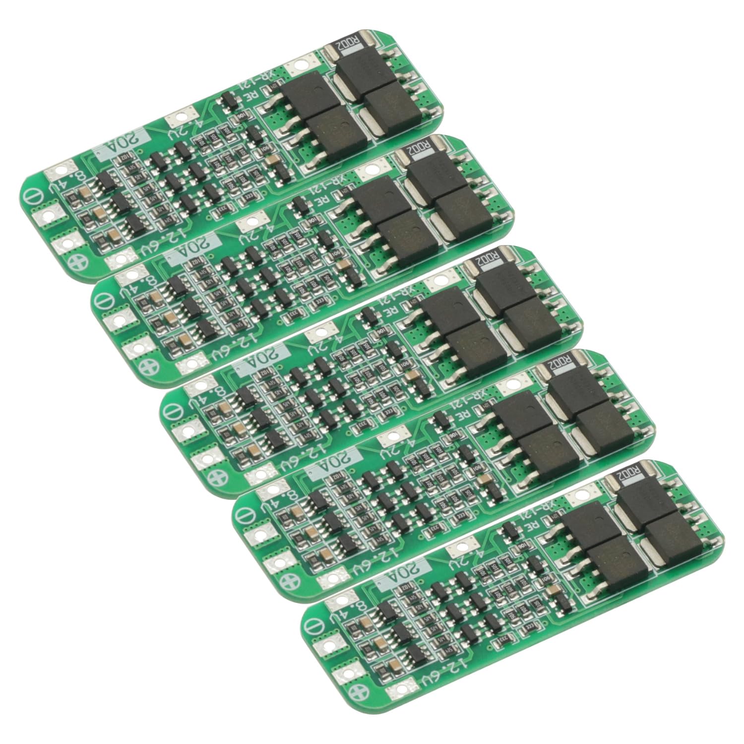
Figure 2.1: Top view of the GODIYMODULES 3S 20A BMS Protection Board. This image shows the compact green PCB with various electronic components and solder points for battery connections.
Key Features:
- Overcharge Protection: Prevents cells from being charged beyond their safe voltage limit.
- Over-discharge Protection: Stops discharge when cells reach their minimum safe voltage.
- Overcurrent Protection: Limits the current drawn from the battery pack to prevent damage.
- Short Circuit Protection: Automatically disconnects the load in case of a short circuit.
- Cell Balancing (Passive): Helps to equalize the voltage across individual cells in the pack (implied by 3S BMS, though not explicitly stated as active balancing).
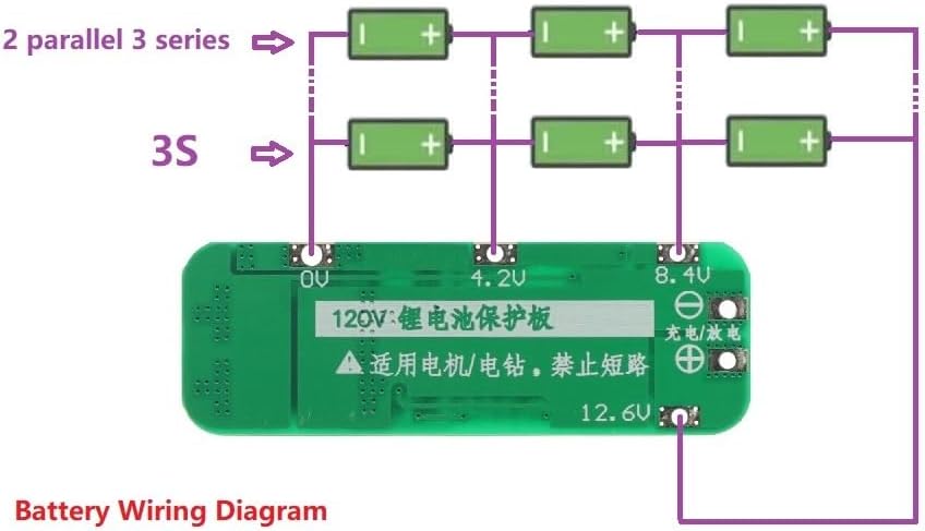
Figure 2.2: Close-up view of the electronic components on the BMS board. This image highlights the integrated circuits, resistors, and capacitors that manage battery protection functions.
3. Specifications
| Feature | Specification |
|---|---|
| Module Name | 3S 12.6V Li-ion Lithium Battery 18650 Charger Protection PCB Board |
| Suitable Battery Type | Nominal 3.6V/3.7V Lithium Battery (18650, 26650, Lithium Polymer) |
| Charging Voltage | 12.6V |
| Maximum Output Current | 20A |
| Product Dimensions | 64mm x 20mm x 3.4mm (approx. 1.98 x 6.4 x 0.33 cm) |
| Material | Metal, PCB |
| Number of Cells | 3 Series (3S) |
4. Setup and Wiring
Correct wiring is critical for the safe and proper operation of the BMS board. Incorrect wiring can damage the board or the battery pack.

Figure 4.1: Wiring diagram for connecting a 3S lithium battery pack to the BMS protection board. This diagram illustrates the connections for 0V, 4.2V, 8.4V, and 12.6V points, as well as the charge/discharge terminals.
Wiring Instructions:
- Identify Connection Points: Locate the 0V, 4.2V, 8.4V, and 12.6V solder points on the BMS board. These correspond to the negative terminal of the first cell, the positive terminal of the first cell (and negative of the second), the positive terminal of the second cell (and negative of the third), and the positive terminal of the third cell, respectively.
- Connect 0V: Connect the negative terminal of your first battery cell (B-) to the 0V point on the BMS board.
- Connect 4.2V: Connect the positive terminal of the first battery cell (B1+) to the 4.2V point on the BMS board. This is also the negative terminal of the second cell.
- Connect 8.4V: Connect the positive terminal of the second battery cell (B2+) to the 8.4V point on the BMS board. This is also the negative terminal of the third cell.
- Connect 12.6V: Connect the positive terminal of the third battery cell (B3+) to the 12.6V point on the BMS board. This is the main positive output/charge terminal.
- Connect Load/Charger: The main charge/discharge terminals are typically labeled P+ and P- or similar. Connect your charger and load to these points. The 12.6V point is usually the main positive output.
Important Precautions for Wiring:
- Strict Adherence: Strictly follow the diagram for wiring 0V/4.2V/8.4V/12.6V. Deviations will cause damage to the chip and potentially the batteries.
- Initial Activation: After all connections are made, the board requires an initial charge activation. Connect a 12.6V charger to the board; this will activate the output.
- Battery Matching: Do not mix new and old batteries, or batteries with significantly different capacities or internal resistances. For optimal performance and safety, the internal resistance and capacity of the three battery cells should be as close as possible.
- Soldering: Ensure all solder joints are clean and secure to prevent intermittent connections or shorts.

Figure 4.2: Close-up of the BMS board showing the clearly marked 0V, 4.2V, 8.4V, and 12.6V connection points, essential for correct battery pack assembly.
5. Operation
Once properly wired and activated, the BMS board operates automatically to protect your battery pack during charging and discharging cycles.
Charging:
- Connect a 12.6V lithium battery charger to the designated charge input terminals (P+ and P-).
- The BMS will manage the charging process, ensuring that individual cells do not overcharge. It will cut off charging if any cell reaches its overcharge protection voltage.
Discharging:
- Connect your load (e.g., drill motor) to the designated output terminals (P+ and P-).
- The BMS will monitor the discharge current and cell voltages. It will cut off the output if the current exceeds 20A (overcurrent protection) or if any cell voltage drops below its over-discharge protection threshold.
6. Precautions and Safety
Adhering to these safety guidelines is crucial to prevent damage to the BMS, batteries, and connected equipment, as well as to ensure personal safety.
- Professional Knowledge: Buyers should possess professional knowledge regarding this module and lithium battery management before purchasing and using.
- Correct Polarity: Always double-check polarity before making any connections. Reverse polarity will instantly damage the BMS board.
- Soldering Safety: Use appropriate soldering techniques and safety equipment. Avoid prolonged heat application to the board components.
- Short Circuit Prevention: Ensure no metal objects or wires can accidentally short circuit the battery terminals or BMS connections.
- Environmental Conditions: Operate the BMS and battery pack within recommended temperature and humidity ranges.
- Battery Health: Use only healthy, matched lithium cells. Damaged or unbalanced cells can lead to performance issues or safety hazards.
- Maximum Current: Do not exceed the maximum continuous discharge current of 20A. Exceeding this limit can cause the BMS to overheat and fail.
7. Troubleshooting
If you encounter issues with your BMS board, consider the following troubleshooting steps:
- No Output After Wiring:
- Ensure the board has been activated by connecting a 12.6V charger for the first time.
- Verify all wiring connections (0V, 4.2V, 8.4V, 12.6V) are correct and secure according to the diagram.
- Check for any short circuits on the output terminals.
- Battery Pack Not Charging:
- Confirm the charger is functioning and providing 12.6V.
- Check if any individual cell voltage is already at its overcharge limit, causing the BMS to cut off charging.
- Inspect charger connections to the BMS.
- Output Cuts Off Unexpectedly:
- This often indicates overcurrent or over-discharge protection. Reduce the load or check individual cell voltages.
- Ensure the load current does not exceed 20A.
- Check if any cell voltage has dropped below its safe discharge limit.
- Verify battery cell health and balance. Unbalanced cells can trigger protection prematurely.
- BMS Board Overheating:
- This usually indicates excessive current draw. Ensure your application's current requirements are within the 20A limit.
- Check for any partial short circuits or faulty components in the load.
8. Maintenance
The GODIYMODULES 3S 20A BMS Protection Board is designed for durability and requires minimal maintenance. However, following these guidelines can help ensure its longevity and reliable performance:
- Keep Clean and Dry: Protect the board from dust, dirt, and moisture. Avoid exposure to liquids.
- Inspect Connections: Periodically check all wiring connections for looseness or corrosion. Re-solder if necessary.
- Avoid Physical Damage: Handle the board carefully to prevent bending, dropping, or other physical impacts.
- Temperature Control: Ensure the operating environment does not expose the board to extreme temperatures.
- Battery Health Monitoring: Regularly monitor the health of your battery cells. A BMS cannot fully compensate for severely degraded or mismatched cells.
9. Warranty and Support
This product is manufactured to high-quality standards. For specific warranty information or technical support, please refer to the seller or manufacturer's official channels. Keep your purchase receipt for any warranty claims.
For further assistance, please contact GODIYMODULES customer support through the platform where the product was purchased.


