Introduction
This manual provides essential instructions for the proper installation, operation, and maintenance of the IHFMPFKJ CV500U2-T01-CB-1 Logic Board Cable. This cable is designed as a replacement or repair component for 50-inch televisions, facilitating the connection between the main logic board and the display panel. Adhering to these guidelines will help ensure the correct function and longevity of your television repair.
Safety Information
Before proceeding with any installation or repair, please read and understand the following safety precautions:
- Disconnect Power: Always unplug the television from the power outlet before opening the back panel or handling any internal components.
- Static Electricity: Electronic components are sensitive to electrostatic discharge (ESD). Use an anti-static wrist strap or frequently touch a grounded metal object to discharge static electricity from your body.
- Handle with Care: Logic board cables are delicate. Avoid bending, twisting, or applying excessive force to the cable or its connectors.
- Professional Assistance: If you are unsure about any step, consult a qualified technician.
Product Overview
The CV500U2-T01-CB-1 is a specialized cable designed to connect the logic board (also known as the T-Con board or main board, depending on TV model) to the display panel within a 50-inch television. It ensures the transmission of video signals and control data necessary for the display to function correctly. This component is crucial for resolving issues related to picture display, such as no image, distorted images, or incorrect colors.

Figure 1: The IHFMPFKJ CV500U2-T01-CB-1 Logic Board Cable. This image shows the flexible flat cable with its connectors, designed for signal transmission within a 50-inch television.
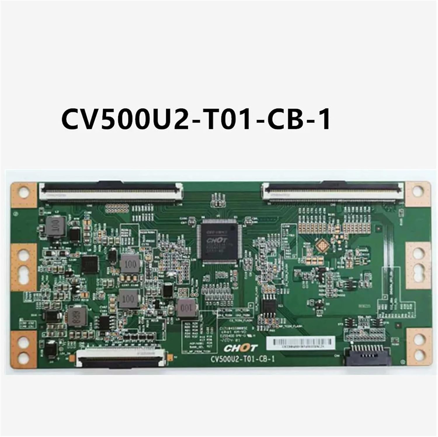
Figure 2: Example of a CV500U2-T01-CB-1 Logic Board. The cable connects to ports on this type of board to transmit signals to the TV's display panel.
Setup and Installation
Follow these steps carefully to install the CV500U2-T01-CB-1 Logic Board Cable:
- Preparation:
- Ensure the television is unplugged from all power sources.
- Place the TV face down on a soft, clean surface to protect the screen.
- Gather necessary tools: Phillips head screwdriver, anti-static wrist strap.
- Accessing Internal Components:
- Remove the screws securing the TV's back panel. Keep track of screw locations as they may vary in size.
- Carefully remove the back panel to expose the internal circuitry.
- Locate Connection Points:
- Identify the logic board (often a smaller board located near the center or top of the TV's internal chassis) and the connection points for the display panel.
- Note the orientation of the existing cable (if replacing) before disconnecting.
- Disconnect Old Cable (if applicable):
- Gently unlatch the connectors on both ends of the old cable. Avoid pulling directly on the wires; instead, use the plastic tabs or edges of the connector.
- Carefully remove the old cable.
- Connect New Cable:
- Align the new CV500U2-T01-CB-1 cable with the connectors on the logic board and the display panel. Ensure the cable is inserted straight and fully into the slots.
- Secure the latches on both connectors to hold the cable firmly in place. Verify that the cable is not twisted or pinched.
- Reassembly and Testing:
- Before fully reassembling the back panel, temporarily plug in the TV and power it on to verify that the display functions correctly.
- If the display is normal, unplug the TV again and reattach the back panel, securing all screws.
Operating
Once the CV500U2-T01-CB-1 Logic Board Cable is correctly installed, the television should power on and display an image as expected. The cable's function is passive, transmitting signals; there are no direct operational controls for the cable itself. Normal TV operation indicates successful installation.
- Power On: Plug the TV into a power outlet and press the power button.
- Verify Display: Check for a clear, stable picture and correct colors.
- Test Inputs: Cycle through different input sources (HDMI, AV, etc.) to ensure full functionality.
Maintenance
The CV500U2-T01-CB-1 Logic Board Cable requires minimal maintenance. To ensure its continued performance:
- Avoid Physical Stress: Do not bend, crimp, or pull on the cable excessively during installation or if the TV is moved.
- Keep Clean: If the TV's back panel is ever removed, ensure the cable and its connectors are free from dust and debris. Use compressed air if necessary.
- Secure Connections: Periodically, if the TV is opened for other repairs, verify that the cable's connectors remain firmly latched.
Troubleshooting
If you encounter issues after installing the CV500U2-T01-CB-1 Logic Board Cable, consider the following:
| Problem | Possible Cause | Solution |
|---|---|---|
| No picture or distorted image | Cable not fully seated or damaged | Disconnect TV power, open back panel, and carefully re-seat both ends of the cable. Inspect the cable for any visible damage. |
| Incorrect colors or flickering display | Loose connection or faulty cable | Ensure cable is securely connected. If the problem persists, the cable may be faulty and require replacement. |
| TV does not power on after installation | Power supply issue or other component failure | Verify the TV is plugged in and the power outlet is functional. This cable is for signal transmission, not power. If the TV doesn't power on, the issue likely lies elsewhere (e.g., power supply board, main board). |
If troubleshooting steps do not resolve the issue, professional assistance may be required.
Specifications
- Model Number: CV500U2-T01-CB-1
- Product Type: Logic Board Cable (TV Accessory)
- Compatibility: Designed for 50-inch televisions (verify compatibility with your specific TV model's logic board).
- Item Weight: 1.76 ounces
- Package Dimensions: 0.39 x 0.39 x 0.39 inches
Warranty and Support
This product is covered by the manufacturer's standard warranty. For specific warranty details, please refer to the documentation provided with your purchase or contact the seller directly. For technical support or further assistance, please reach out to the IHFMPFKJ customer service team through your purchase platform.