1. Introduction
This manual provides essential information for the safe and effective operation of the NICGQMQR ES-F300 series Variable Frequency Drive (VFD). The ES-F300 is designed to control the speed of AC motors, offering precise control and various protective functions. Please read this manual thoroughly before installation, operation, or maintenance.

Figure 1: ES-F300 VFD Motor Speed Controller, showing the control panel and terminal block.
2. Safety Precautions
WARNING: Failure to follow these safety precautions may result in serious injury or equipment damage.
- Before wiring, ensure that the input power to the VFD is completely disconnected and locked out.
- All wiring work must be performed by a qualified and professional electrical engineer.
- The grounding terminals of the VFD must be properly connected to a reliable earth ground.
- In case of an emergency stop or circuit wiring pause, verify that the safety check is effective before resuming work.
- Do not connect the output wire of the inverter directly to the VFD's casing or ground. Ensure proper insulation and connections.
3. Specifications
3.1. General Specifications
- Item Weight: 50 Grams
- Number of Pieces: 1
- Manufacturer: NICGQMQR
3.2. Electrical Specifications
| Parameter | ES-F300S VFD | ES-F300T VFD |
|---|---|---|
| Input Voltage (AC) | 1-phase 220V; 50/60Hz 3-phase 220V; 50/60Hz | 3-phase 380-440V; 50/60Hz |
| Input Voltage (DC) | DC200-400V | DC380-700V |
| Output Voltage | 3-phase; 0-240V | 3-phase; 0-440V |
| Control Mode | V/F control, No PG vector control (sensorless vector control, open loop vector control) | |
| Built-in Features | Built-in PID control (for user pressure control, constant output pressure) | |
| Braking Unit | No braking unit | |
3.3. Input/Output Interfaces
- Logic Input: 5 terminals (X1-X5) for functions such as positive/negative rotation, jogging, multi-speed control, and terminal UP/DOWN frequency given.
- Analog Input (AVI): 0-10V (voltage signal) for frequency setting.
- Analog Input (ACI): 0-20mA (current signal) for frequency setting.
- Analog Output (A01): 0-10V (voltage signal) for operating frequency, output current indication, etc.
- Relay Output: TA/TB/TC (normally open, normally closed contacts).
4. Setup and Installation
Proper installation and wiring are crucial for the safe and reliable operation of the VFD. Refer to the following diagrams for typical wiring configurations.
4.1. Wiring for Three-Phase Motor with Single-Phase AC220V Input
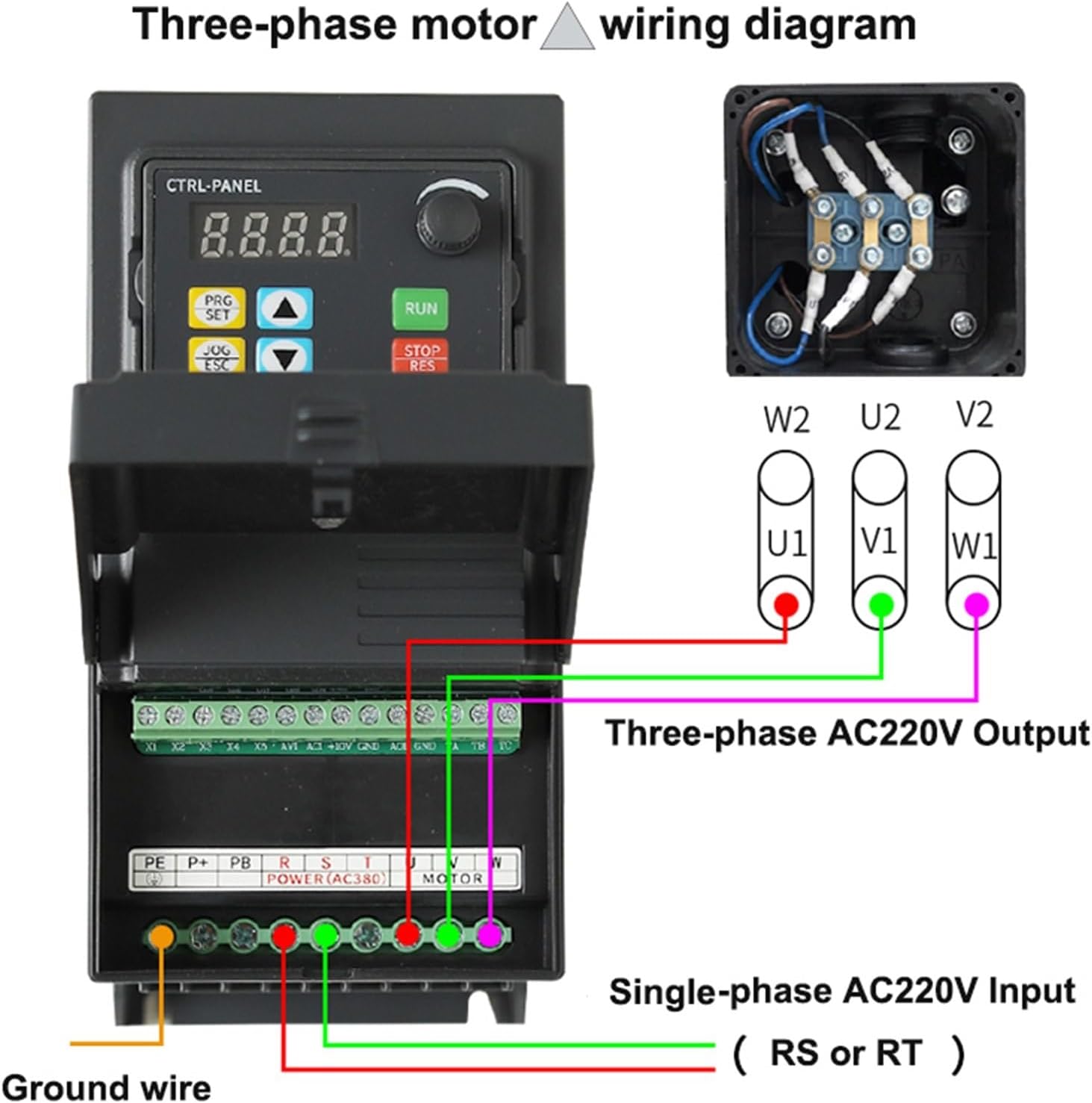
Figure 2: Wiring diagram showing single-phase AC220V input (RS or RT) to the VFD and three-phase AC220V output (U, V, W) to the motor. Includes ground wire connection.
4.2. Wiring for Three-Phase Motor (Y-connection) with Three-Phase AC380V Input

Figure 3: Wiring diagram showing three-phase AC380V input (RST) to the VFD and three-phase AC380V output (U, V, W) to the motor in a Y-connection. Includes ground wire connection.
Ensure all connections are secure and insulated. Verify input voltage matches the VFD model (e.g., ES-F300S for 220V input, ES-F300T for 380V input).
5. Operating Instructions
The ES-F300 VFD primarily uses V/F control for motor speed regulation. The control panel allows for parameter adjustment and operational control.
5.1. Control Panel Overview
The control panel features a digital display (4-digit) and several buttons for programming and operation:
- PRG/SET: Program/Set button for entering and confirming parameter settings.
- JOG/ESC: Jog/Escape button for momentary operation or exiting menus.
- UP/DOWN Arrows: For navigating menus and adjusting parameter values.
- RUN: Starts the motor.
- STOP/RES: Stops the motor or resets faults.
5.2. Control Modes
- V/F Control: This is the standard control method, maintaining a constant voltage-to-frequency ratio to ensure stable motor flux.
- No PG Vector Control (Sensorless Vector Control, Open Loop Vector Control): Provides improved speed regulation and torque control without the need for an encoder.
- Built-in PID Control: Allows the VFD to maintain a constant output (e.g., pressure, flow) by automatically adjusting motor speed based on feedback. This is useful for applications requiring precise process control.
5.3. Frequency Setting
Frequency can be set via the control panel using the UP/DOWN arrows, or externally via analog inputs (AVI for 0-10V voltage signal, ACI for 0-20mA current signal).
6. Maintenance
Regular maintenance helps ensure the longevity and optimal performance of your VFD. While specific maintenance procedures are not detailed, general guidelines include:
- Keep the VFD clean and free from dust and debris.
- Ensure adequate ventilation to prevent overheating.
- Periodically check all wiring connections for tightness and signs of wear or corrosion.
- Inspect cooling fans for proper operation and cleanliness.
- Avoid exposing the VFD to excessive moisture or corrosive environments.
For any complex maintenance or repair, contact a qualified technician or the manufacturer.
7. Troubleshooting
The ES-F300 VFD is equipped with various protective functions that can indicate a fault condition. If the VFD stops operating or displays an error, refer to the following common protective functions:
- Overcurrent: Indicates excessive current draw, possibly due to motor overload or short circuit.
- Overvoltage: Input voltage exceeds safe limits.
- Undervoltage: Input voltage drops below safe operating limits.
- Module Fault: Internal power module issue.
- Electric Thermal Relay: Motor thermal overload protection activated.
- Overheat: VFD internal temperature is too high.
- Short Circuit: Short circuit detected in the output wiring or motor.
- Default Phase of Input and Output: Missing phase in input or output power.
- Motor Parameter Adjustment Abnormality: Incorrect motor parameters configured.
- Internal Memory Fault: Issue with the VFD's internal memory.
When a fault occurs, the VFD display will typically show an error code. Consult the full product manual (if available from the manufacturer) for specific error code interpretations and detailed troubleshooting steps. Always disconnect power before inspecting the VFD or its connections.
8. Warranty and Support
Specific warranty details for the NICGQMQR ES-F300 VFD are not provided in this document. For information regarding warranty coverage, technical support, or service, please contact the seller or the manufacturer directly using the contact information provided at the point of purchase.
It is recommended to keep your purchase receipt as proof of purchase for warranty claims.