1. Introduction
This manual provides detailed instructions for the installation, operation, and maintenance of the NQODRNDQ HS800-3 3 Axis LCD Digital Readout (DRO) system and its accompanying linear scale encoders. This system is designed to enhance precision and efficiency in various machine tools such as milling machines, lathes, drills, and boring machines by providing accurate real-time position feedback.
2. Safety Information
Always observe the following safety precautions to prevent injury and damage to the equipment:
- Ensure the power supply matches the specified input voltage (AC80-250V 50/60HZ).
- Disconnect power before performing any installation, maintenance, or cleaning.
- Avoid exposing the DRO unit or linear scales to excessive moisture, dust, or extreme temperatures.
- Handle linear scales with care to prevent bending or damage to the reading head and glass grating.
- Secure all cables to prevent entanglement with moving machine parts.
3. Package Contents
Verify that all components are present and undamaged upon unpacking:
- HS800-3 3 Axis LCD Digital Readout Display Unit
- 3 Pieces High Precision Linear Scale Encoders (50mm-1000mm travel length, 5um resolution)
- Power Cable
- Display Cover
- Mounting Bracket for DRO
- Mounting Hardware for Linear Scales
- User Manual (this document)

Image 3.1: Overview of the NQODRNDQ HS800-3 Digital Readout system and its components, including the display unit, linear scales, cables, and mounting accessories.
4. Specifications
| Feature | Specification |
|---|---|
| Model Number | HS800-3 |
| Procut Name | 3 Axis LCD DRO kit |
| Input Voltage | AC80-250V 50/60HZ |
| Signal Type | TTL |
| Power Consumption | 25VA |
| Output Voltage | 5VDC |
| Resolution | 5um (0.001mm) |
| Scale Travel Length | 50mm - 1000mm |
| Scale Cable Length | 3 meters |
| Application | Lathe, Mill, Drill, Boring machine etc. |
5. Setup and Installation
5.1. Mounting the DRO Display Unit
Select a suitable location on your machine tool for the DRO display unit. The location should provide clear visibility, easy access to controls, and protection from coolant or debris. Use the provided mounting bracket and hardware to securely attach the display unit.

Image 5.1: Front view of the HS800-3 DRO display unit, showing the LCD screen and control buttons.
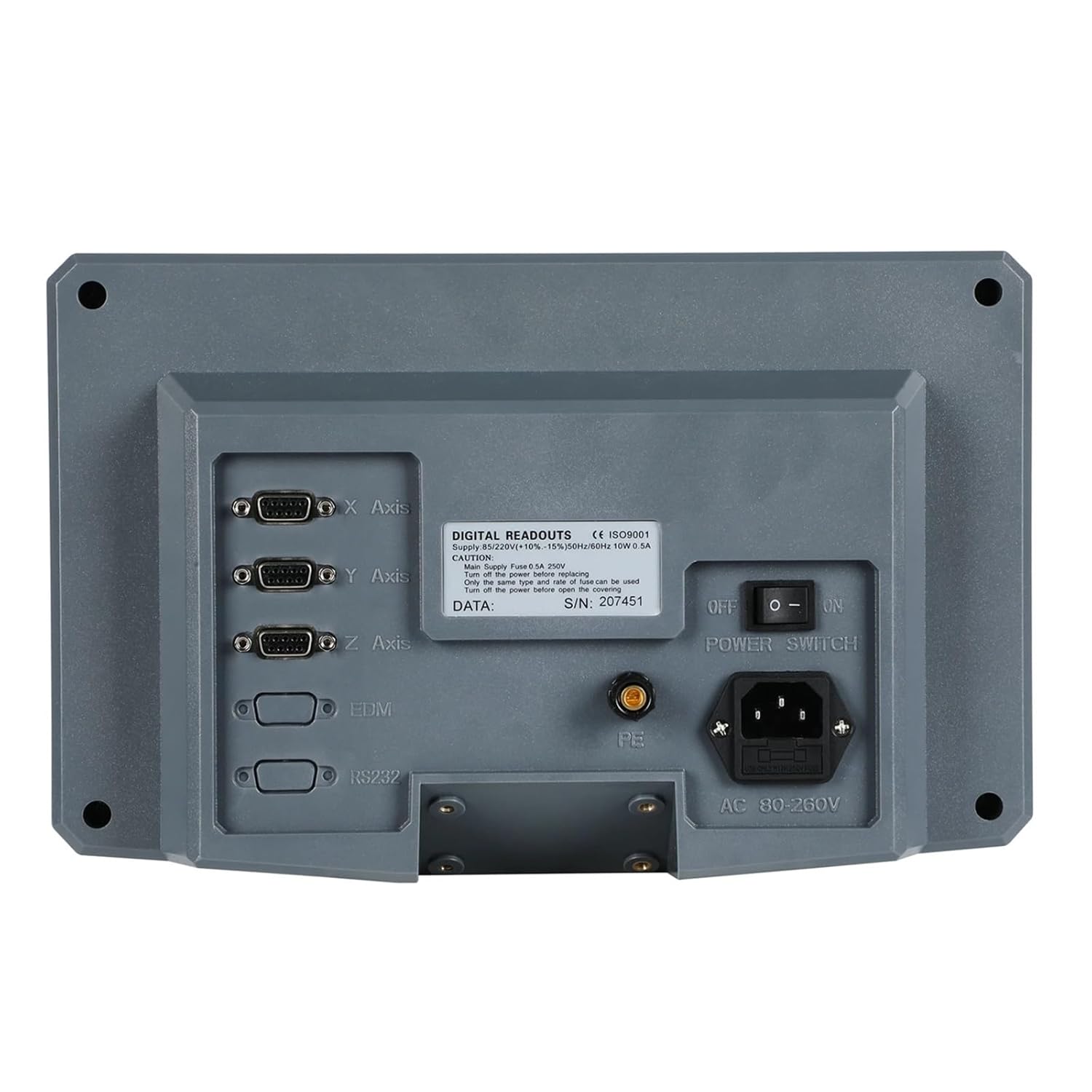
Image 5.2: Rear view of the HS800-3 DRO display unit, illustrating the connection ports for X, Y, Z axes, EDM, RS232, power input, and the power switch.
5.2. Installing Linear Scale Encoders
Install each linear scale encoder parallel to the axis of motion it will measure. Ensure the reading head moves freely along the scale without binding. Use the provided mounting hardware to secure the scale body and the reading head bracket. Maintain a small, consistent gap between the reading head and the scale grating as specified in the scale's individual instructions.
- Mount the scale body securely to the stationary part of the machine.
- Attach the reading head bracket to the moving part of the machine.
- Align the reading head to the scale, ensuring proper clearance.
- Route the scale cables carefully to avoid interference with machine operation.

Image 5.3: A single linear scale encoder, showing the scale body and the attached reading head with its protective cable.

Image 5.4: A linear scale encoder displayed with its associated mounting brackets and screws, essential for secure installation on a machine tool.

Image 5.5: The HS800-3 DRO display unit shown connected to three linear scale encoders, illustrating a typical setup for a 3-axis machine.
5.3. Connecting Linear Scales to DRO
Connect the cables from each linear scale to the corresponding X, Y, and Z axis ports on the back of the HS800-3 DRO unit. Ensure the connectors are fully seated and secured. The ports are clearly labeled for each axis.
5.4. Power Connection
Connect the provided power cable to the AC input port on the back of the DRO unit. Plug the other end into a compatible AC80-250V 50/60HZ power outlet. Ensure the power switch on the back of the DRO is in the 'OFF' position before connecting power.
6. Operating Instructions
6.1. Powering On/Off
- To power on, flip the power switch on the back of the DRO unit to the 'ON' position. The LCD screen will illuminate and display the axis readings.
- To power off, flip the power switch to the 'OFF' position.
6.2. Basic Functions
The DRO unit features a clear LCD display and a keypad for various functions:
- Axis Display: The large digits on the screen show the current position for X, Y, and Z axes.
- MM/INCH: Press the 'UNIT' button (often labeled 'MM/INCH' or similar) to toggle between millimeter and inch display modes.
- ABS/INC: Use the 'ABS/INC' button to switch between Absolute and Incremental coordinate modes. Absolute mode displays positions relative to a fixed datum, while Incremental mode displays positions relative to a temporary zero point.
- Zero Set: To set the current position of an axis to zero, press the corresponding axis button (e.g., 'X', 'Y', 'Z') followed by the '0' or 'ZERO' button.
- Numeric Input: The numeric keypad (0-9) and 'Ent' button are used for entering values for functions like setting coordinates or tool offsets.
6.3. Advanced Features (F1-F6 Keys)
The function keys F1 through F6 provide access to various advanced features. The specific functions assigned to these keys may vary based on the DRO's firmware version and configuration. Refer to the on-screen prompts or the detailed user manual (if provided separately) for specific operations such as:
- Hole pattern calculations
- Arc processing
- Tool compensation
- Radius/Diameter display
- Setting parameters (Setup)
7. Maintenance
Regular maintenance ensures the longevity and accuracy of your DRO system:
- Cleaning: Keep the DRO display unit and linear scales clean. Use a soft, dry cloth to wipe surfaces. For scales, ensure the glass grating is free of dust, oil, and debris. Avoid abrasive cleaners or solvents.
- Cable Inspection: Periodically check all cables for signs of wear, cuts, or damage. Replace damaged cables immediately.
- Mounting Security: Verify that all mounting brackets and hardware for both the DRO unit and linear scales remain tight and secure.
- Scale Alignment: Ensure the linear scales remain properly aligned and the reading heads move smoothly without excessive friction or play.
8. Troubleshooting
If you encounter issues with your NQODRNDQ HS800-3 DRO system, consider the following:
| Problem | Possible Cause | Solution |
|---|---|---|
| DRO does not power on | No power supply; Power switch off; Faulty cable | Check power connection; Ensure switch is ON; Test power cable. |
| Axis display shows '---' or erratic readings | Loose scale connection; Damaged scale cable; Dirty scale grating; Misaligned reading head | Check scale cable connection; Clean scale grating; Verify reading head alignment. |
| Incorrect measurements | Incorrect unit setting (mm/inch); Scale resolution mismatch; Calibration error | Verify unit setting; Check DRO parameters for scale resolution; Recalibrate if necessary. |
| Buttons unresponsive | System freeze; Hardware fault | Power cycle the DRO unit; Contact support if issue persists. |
9. Warranty and Support
For warranty information, technical support, or service inquiries, please refer to the contact details provided with your purchase documentation or visit the official NQODRNDQ website. Keep your purchase receipt as proof of purchase for warranty claims.