1. Product Overview
The HABOTEST HT118L is a professional-grade digital multimeter designed for accurate and reliable electrical measurements. It features 6000 counts, True RMS capabilities, and a wide range of functions including NCV (Non-Contact Voltage) detection and Live Wire detection. This versatile tool is essential for electricians, electronics enthusiasts, and anyone requiring precise electrical diagnostics.

Figure 1: HABOTEST HT118L Digital Multimeter. This image displays the front view of the multimeter, showcasing its display, rotary dial, function buttons, and input terminals.
Key Features:
- Accurate Measurement: 6000 counts for precise readings, ensuring reliable electrical measurements.
- Versatile Functions: Includes inductance measurement, NCV, Live Wire detection, diode test, continuity, and more.
- User-Friendly Design: Intelligent auto-ranging and one-handed operation for convenient usage.
- Durable Construction: Made with robust ABS material and features a shock-resistant rubber protective case for long-lasting performance.
- Enhanced Safety: Built-in dual ceramic fuses provide protection against high-voltage measurements.
2. Safety Information
Always adhere to safety precautions when operating the multimeter to prevent personal injury or damage to the device. This multimeter is designed to meet safety standards EN61010-1, -2-030; EN61010-2-033, EN61326-1, CAT I 1000V, CAT IV 600V.
General Safety Guidelines:
- Do not exceed the maximum input values for any function.
- Ensure the test leads are properly connected and in good condition before use.
- Do not use the multimeter if it appears damaged or if the insulation on the test leads is compromised.
- Always turn off the circuit power before connecting or disconnecting test leads for current measurements.
- Be cautious when working with voltages above 30V AC RMS, 42V peak, or 60V DC, as they pose a shock hazard.
- Replace batteries promptly when the low battery indicator appears to ensure accurate readings.
- The device features dual ceramic fuses for enhanced protection. Do not attempt to bypass or replace them with incorrect types.
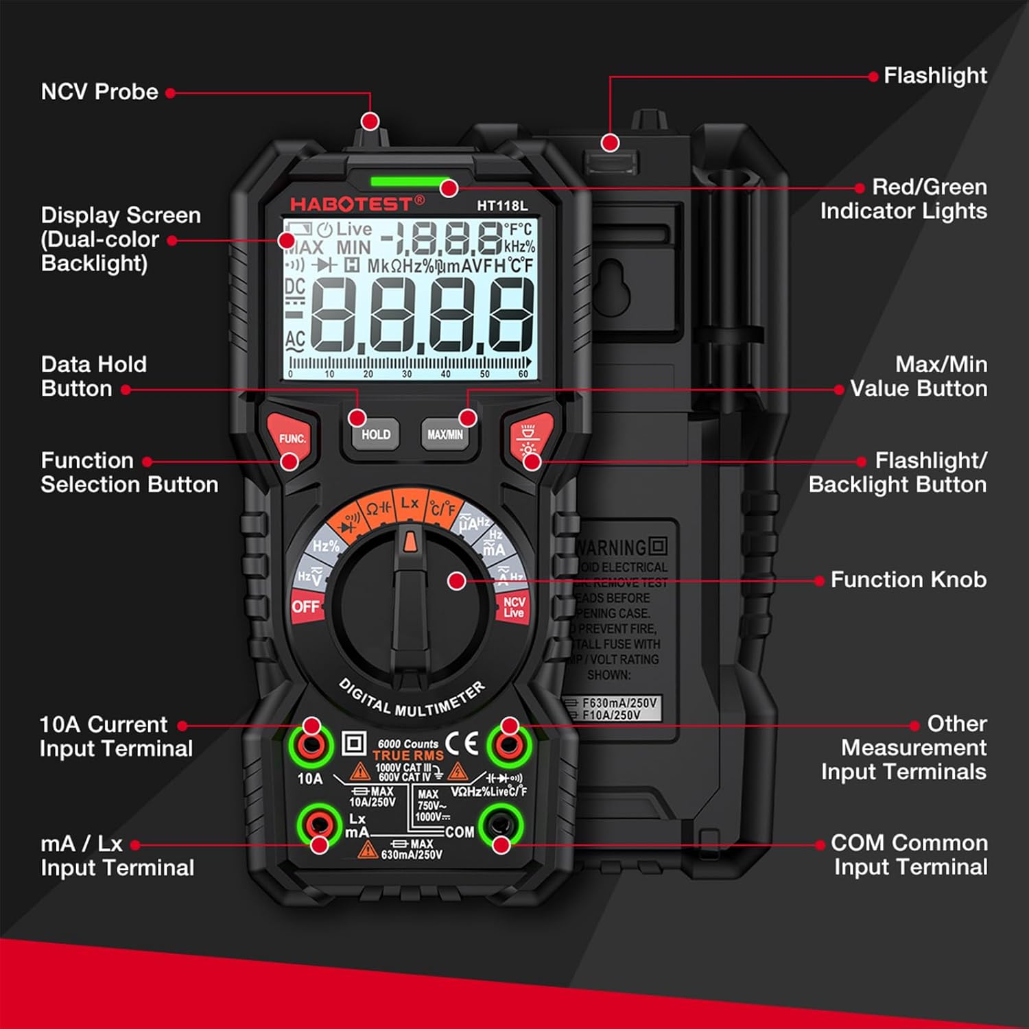
Figure 2: Product Safety and Reliability. This image highlights the multimeter's shock-resistant rubber protective case and its safety ratings, emphasizing durability and user safety.

Figure 3: Dual Ceramic Fuses. This image shows the internal circuit board of the multimeter, highlighting the dual ceramic fuses designed for enhanced protection during high-voltage measurements.
3. Setup and Initial Operation
3.1. Package Contents
Before starting, ensure all items are present in the package:
- 1 x HABOTEST HT118L Digital Multimeter
- 1 x Pair of Test Leads
- 1 x K-type Thermocouple (for temperature measurement)
- 1 x User Manual

Figure 4: Complete Package. This image displays the multimeter alongside its packaging box, test leads, and user manual, indicating all included components.
3.2. Battery Installation
The multimeter requires 2 x 1.5V AA batteries (not included). To install:
- Locate the battery compartment cover on the back of the multimeter.
- Use a screwdriver to open the cover.
- Insert the two AA batteries, ensuring correct polarity (+/-).
- Replace the battery compartment cover and secure it.
3.3. Connecting Test Leads
Always connect the black test lead to the "COM" (Common) input terminal. Connect the red test lead to the appropriate input terminal based on the measurement function:
- VΩHz%CAP°C°F: For Voltage, Resistance, Frequency, Capacitance, and Temperature measurements.
- mA/µA: For milliampere and microampere current measurements.
- 10A: For high current measurements (up to 10 Amperes).
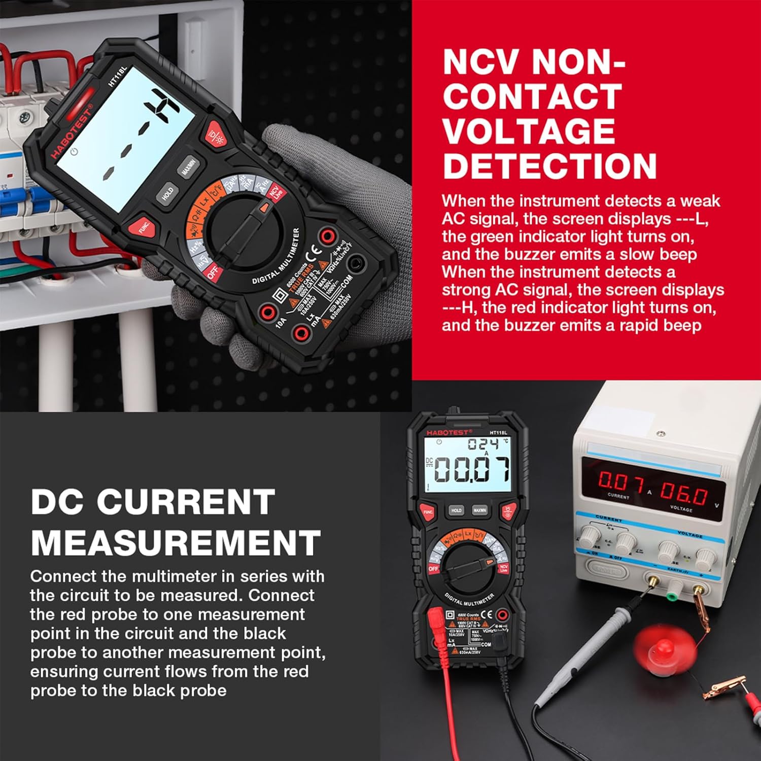
Figure 5: Multimeter Components. This image provides a detailed diagram of the multimeter's front panel, labeling key components such as the display screen, function selection button, input terminals, and NCV probe.
4. Operating Instructions
4.1. General Operation
- Turn the rotary dial to the desired measurement function.
- Connect the test leads to the circuit or component being measured.
- Read the measurement value on the LCD dual display. The analog bargraph provides a quick visual indication of changing values.

Figure 6: Dual Display + Analog Progress Bar. This image illustrates the multimeter's display, showing both digital readings and an analog bar graph, which is particularly useful for visualizing AC voltage fluctuations.
4.2. Measurement Functions
The HT118L offers a comprehensive set of measurement capabilities:
- AC/DC Voltage Measurement (V~, V-): Select the appropriate voltage range. Connect leads in parallel with the circuit.
- AC/DC Current Measurement (A~, A-): Select the appropriate current range. Connect leads in series with the circuit.
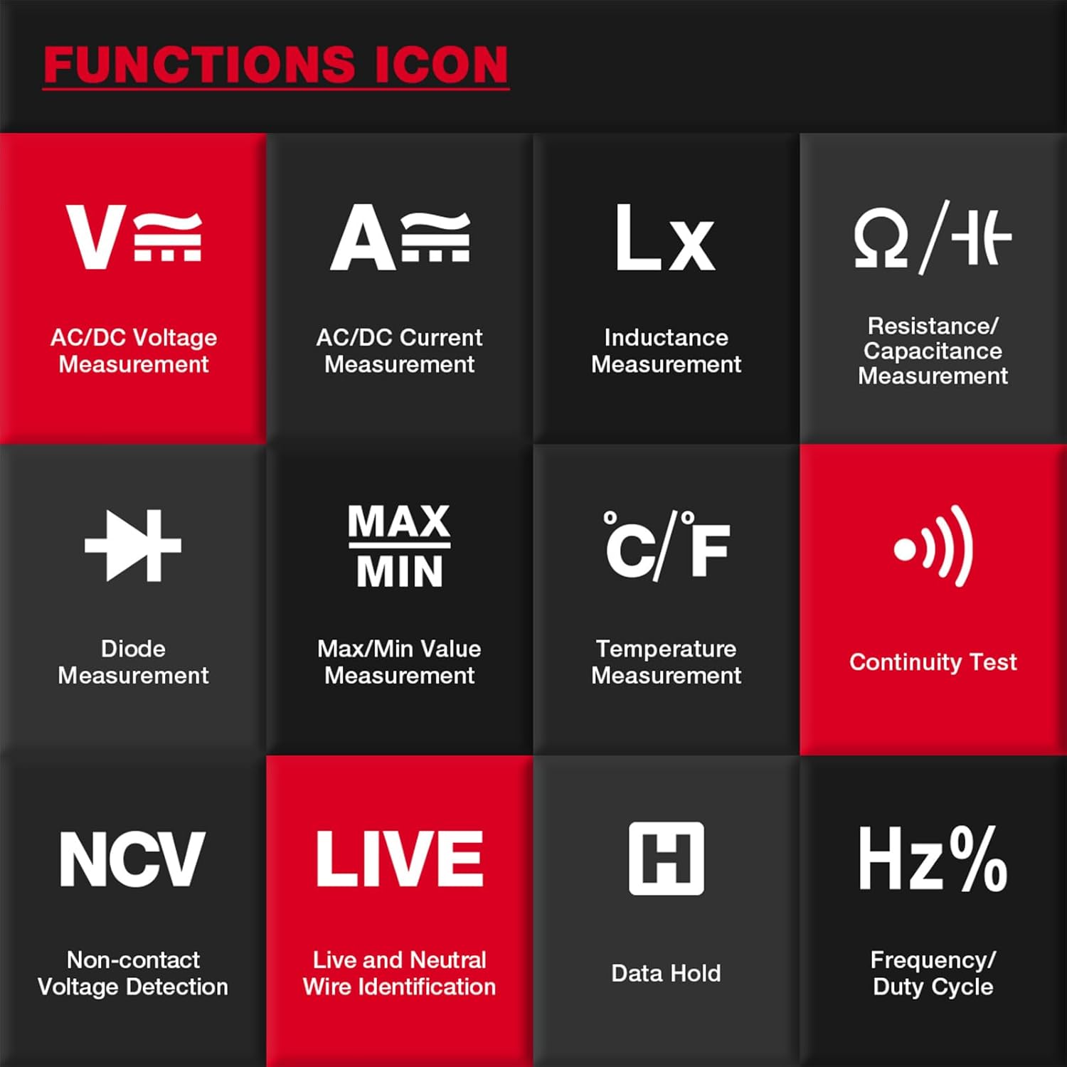
Figure 7: DC Current Measurement. This image demonstrates how to connect the multimeter in series to measure DC current, showing the red probe connected to one point and the black probe to another to ensure current flow.
- Resistance Measurement (Ω): Turn the dial to the Ohm symbol. Ensure the circuit is de-energized before measuring resistance.
- Capacitance Measurement (F): Select the capacitance function. Ensure capacitors are discharged before testing.
- Frequency/Duty Cycle (Hz%): Used for measuring the frequency and duty cycle of AC signals.
- Temperature Measurement (°C/°F): Connect the K-type thermocouple to the appropriate terminals.
- Diode Measurement (▶|): Used to test the forward voltage drop of diodes.
- Continuity Test ()))): Emits an audible beep if the resistance is below a certain threshold, indicating continuity.
- Inductance Measurement (Lx): Used for measuring the inductance of coils and inductors.
- Non-Contact Voltage (NCV) Detection: Hold the NCV probe near a live wire. The display will show "---L" for weak AC signals (green indicator, slow beep) and "---H" for strong AC signals (red indicator, rapid beep).
Figure 8: NCV Non-Contact Voltage Detection. This image shows the multimeter's NCV function in use, detecting voltage without direct contact, with the display indicating the presence of an AC signal.
- Live Wire Identification (LIVE): Helps identify live and neutral wires.
4.3. Special Functions
- Data Hold (HOLD): Press the "HOLD" button to freeze the current reading on the display. Press again to release.

Figure 9: Data Hold Function. This image illustrates the activation of the data hold mode, allowing users to conveniently view and record measurement results without the reading changing.
- Max/Min Hold (MAX/MIN): Press the "MAX/MIN" button to record the maximum and minimum values during a measurement session.
- Auto Power-Off: To conserve battery life, the multimeter will automatically shut down after approximately 15 minutes of inactivity. Press any key to resume operation.
Figure 10: Auto Power-Off. This image demonstrates the multimeter's auto power-off feature, which activates after 15 minutes of no operation to conserve battery power.
- Backlight/Work Light: Press the light button to activate the display backlight or the integrated work light for improved visibility in low-light conditions.
- Input Jack LED Indicate: LEDs near the input jacks illuminate to guide correct lead connection for the selected function.
5. Maintenance
5.1. Cleaning
To clean the multimeter, use a soft, damp cloth and a mild detergent. Do not use abrasive cleaners or solvents. Ensure the device is powered off and disconnected from any circuits before cleaning.
5.2. Battery Replacement
When the low battery indicator appears on the display, replace the batteries promptly to ensure accurate measurements. Refer to section 3.2 for battery installation instructions.
5.3. Fuse Replacement
The multimeter is protected by dual ceramic fuses. If the current measurement function stops working, the fuse may need replacement. Fuse replacement should only be performed by qualified personnel. Ensure the multimeter is disconnected from all power sources and test leads before attempting to open the casing. Refer to the specifications for correct fuse ratings (600mA/250V for mA range, 10A/250V for 10A range).
5.4. Storage
When not in use for extended periods, remove the batteries to prevent leakage. Store the multimeter in a cool, dry place, away from direct sunlight and extreme temperatures.
6. Troubleshooting
If you encounter issues with your HABOTEST HT118L Digital Multimeter, refer to the following common problems and solutions:
| Problem | Possible Cause | Solution |
|---|---|---|
| No display or weak display | Dead or low batteries; Incorrect battery polarity. | Replace batteries with new 1.5V AA batteries; Ensure correct battery polarity. |
| No reading for current measurement | Blown fuse; Incorrect connection (not in series); Wrong range selected. | Check and replace fuse if necessary (refer to section 5.3); Connect multimeter in series with the circuit; Select appropriate current range. |
| "OL" (Overload) displayed | Input value exceeds selected range; Open circuit (for resistance/continuity). | Select a higher range; Check for open circuit or broken wires. |
| Inaccurate readings | Low battery; Environmental interference; Damaged test leads. | Replace batteries; Move away from strong electromagnetic fields; Inspect and replace test leads if damaged. |
| Multimeter automatically shuts off | Auto Power-Off feature activated due to inactivity. | This is normal behavior. Press any button to resume operation. |
7. Specifications
| Parameter | Specification |
|---|---|
| Model | HT118L |
| Counts | 6000 |
| Display | LCD Dual Display with Bargraph |
| DC Voltage | 600mV/6V/60V/600V/1000V, ±(0.5%+3) |
| AC Voltage | 600mV/6V/60V/600V/750V, ±(0.8%+5) |
| DC Current | 600µA/6000µA/60mA/600mA/10A, ±(1.2%+3) |
| AC Current | 600µA/6000µA/60mA/600mA/10A, ±(1.5%+3) |
| Resistance | 600Ω/6kΩ/60kΩ/600kΩ, ±(1.0%+3); 6MΩ/60MΩ, ±(1.5%+3) |
| Capacitance | 10nF/100nF/1000nF/10µF/100µF/1000µF, ±(4.0%+5); 10mF/100mF, ±(5.0%+5) |
| Frequency | 10Hz/100Hz/1000Hz/10kHz/100kHz/1000kHz/10MHz, ±(1.0%+10) |
| Duty Cycle | 1%~99%, ±(3.0%+3) |
| Temperature | -20℃ ~ 0℃ (±5.0% ±3℃); 0℃ ~ 400℃ (±1.0% ±2℃); 400℃ ~ 1000℃ (±2.0%) -4℉ ~ 32℉ (±5.0% ±6℉); 32℉ ~ 752℉ (±1.0% ±4℉); 752℉ ~ 1832℉ (±2.0%) |
| Inductance Measurement | 2mH/20mH/200mH, ±(2.0%+8); 2H, ±(5.0%+5); 20H, ±(5.0%+15); 200H, ---- |
| Power | 2 * 1.5V AA batteries |
| Safety Rating | EN61010-1, -2-030; EN61010-2-033, EN61326-1, CAT I 1000V, CAT IV 600V |
| Item Size | 190 * 88 * 53mm / 7.48 * 3.46 * 2.08in |
| Item Weight | 323g / 11.39oz |
| Material | ABS |
| Manufacturer | Multi-Wits |
| Model Number | Multi-Wits4c3oyvbdhr |
8. Warranty and Support
For warranty information or technical support, please refer to the contact details provided with your purchase or visit the official Multi-Wits website. Keep your purchase receipt as proof of purchase for any warranty claims.