1. Introduction
This manual provides essential information for the safe operation, assembly, maintenance, and troubleshooting of your BUCKTOOL 12'' 6 Pole Motor Variable Speed Benchtop Drill Press. Please read and understand all instructions before operating the machine to ensure personal safety and optimal performance.
Important Safety Information: Always wear appropriate personal protective equipment (PPE) including safety glasses. Ensure the workpiece is securely clamped before drilling. Disconnect power before making adjustments or performing maintenance.
2. Product Overview and Components
Familiarize yourself with the main components of your drill press for proper operation and maintenance.
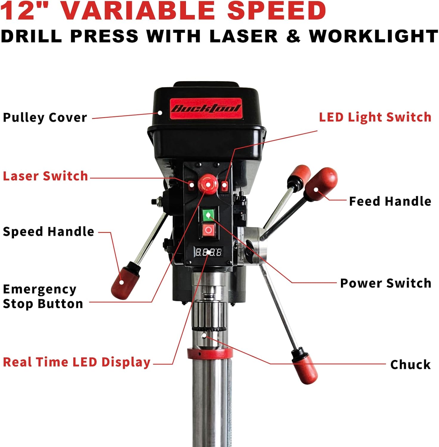
Image 2.1: Labeled components of the BUCKTOOL 12-inch Benchtop Drill Press. Key components include the Pulleys Cover, LED Light Switch, Laser Switch, Speed Handle, Emergency Stop Button, Real Time LED Display, Chuck, Feed Handle, and Power Switch.

Image 2.2: View of the powerful 6-pole motor, designed for low speed and high torque applications.
3. Specifications
The BUCKTOOL 12'' 6 Pole Motor Variable Speed Benchtop Drill Press is engineered for precision and durability in both metalworking and woodworking applications.
- Motor: Powerful 6-pole motor, 3/4 HP
- Speed Range: Variable, 360-2000 RPM (real-time LED digital readout)
- Chuck Capacity: 1/32" - 5/8"
- Swing: 12 inches
- Spindle Travel: 2 inches (3-1/8" indicated in image)
- Worktable: ±45° tilt-able with angle guide, 9-17/32" x 9-17/32" size
- Features: Built-in laser, LED work light
- Input: 120VAC, 60Hz
- Product Dimensions: 84 x 53.49 x 33.02 cm (33.07 x 21.06 x 13 inches)
- Item Weight: 41.3 kg (91 lbs)

Image 3.1: Visual representation of key specifications including input, chuck size, motor amperage, speed range, swing, spindle travel, table size, and table movement.
4. Setup
Carefully unpack all components and ensure all parts are present before beginning assembly. Assembly typically involves securing the base, attaching the column, mounting the drill press head, and installing the worktable and chuck.
- Base Installation: Secure the drill press base to a sturdy workbench using appropriate fasteners.
- Column Assembly: Attach the column to the base, ensuring it is vertical and securely fastened.
- Head Assembly: Mount the drill press head onto the column. Ensure all locking mechanisms are tightened.
- Worktable Installation: Install the worktable and its support arm onto the column. Adjust to a comfortable working height and lock it in place.
- Chuck Installation: Clean the tapered spindle and the inside of the chuck. Place the chuck onto the spindle and tap it firmly with a rubber mallet to seat it properly.
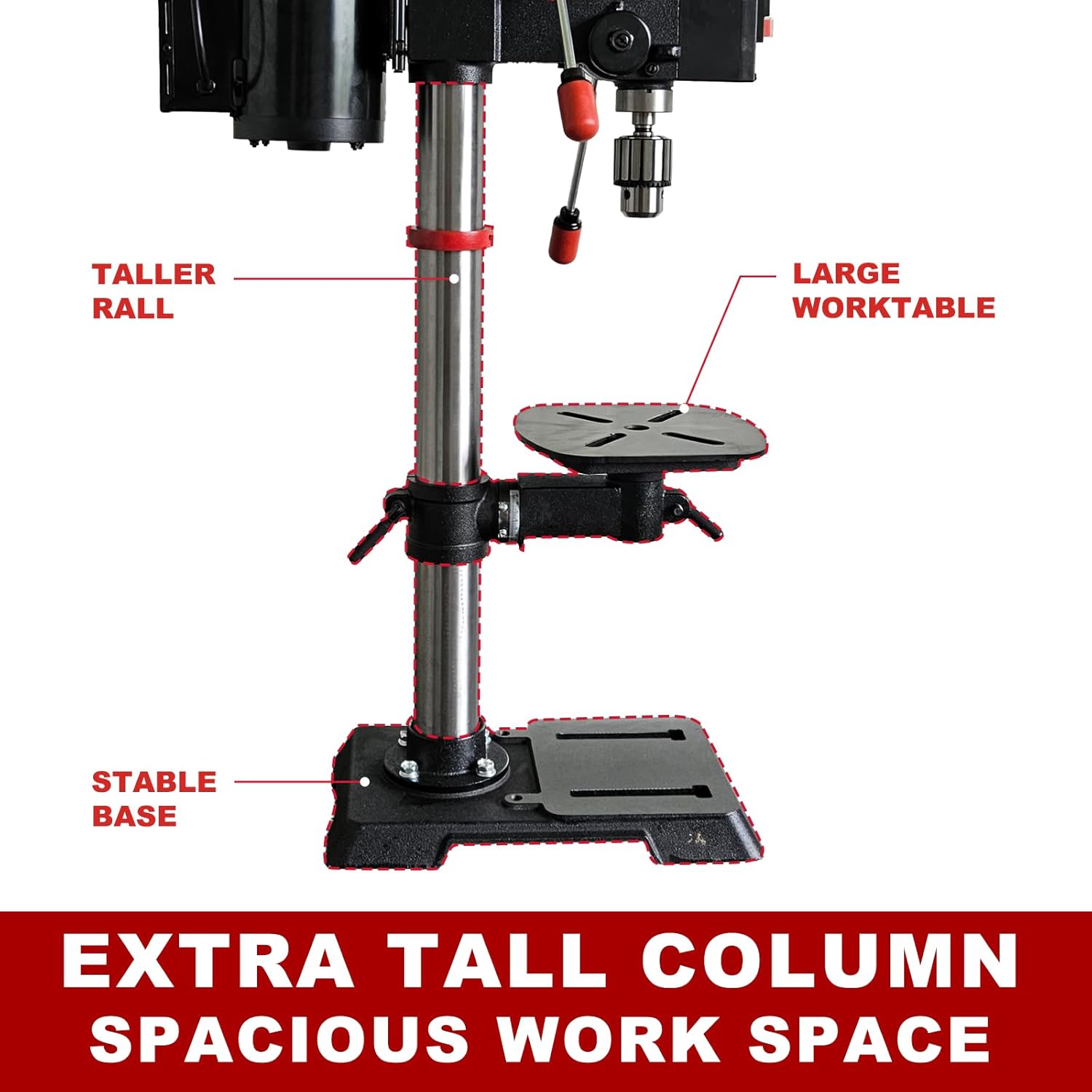
Image 4.1: Illustration of the drill press's stable structure, featuring an extra tall column for increased vertical clearance and a large worktable for accommodating various material sizes.
5. Operating Instructions
5.1 Powering On/Off
- Power Switch: Locate the main power switch on the drill press head. Press to turn the machine on or off.
- Emergency Stop Button: In case of an emergency, press the red emergency stop button to immediately cut power to the motor. Twist to reset.
5.2 Speed Adjustment
The drill press features variable speed control from 360 to 2000 RPM, suitable for various materials.
- Speed Handle Dial: Use the speed handle dial to adjust the RPM.
- LED Digital Readout: Monitor the current RPM in real-time on the LED display.
- Recommended Speeds: Lower speeds (e.g., 360 RPM) are ideal for metal, while higher speeds (e.g., 2000 RPM) are suitable for plastics. Wood and jade typically use intermediate speeds.

Image 5.1: Guide for selecting appropriate variable speeds (360-2000 RPM) for drilling different materials such as metal, jade, wood, and plastic.
5.3 Worktable Adjustment
- Height Adjustment: Loosen the worktable lock and use the crank to move the table up or down the column. Retighten the lock.
- Tilt Adjustment: The worktable can tilt ±45°. Loosen the tilt lock, adjust the angle using the angle guide, and retighten.
5.4 Laser and Worklight
The integrated laser and LED work light enhance drilling accuracy and visibility.
- Laser Switch: Activate the laser to project crosshairs onto your workpiece, indicating the drill point.
- LED Light Switch: Turn on the LED work light to illuminate the drilling area, reducing shadows.

Image 5.2: View of the onboard worklight and laser system, designed for precise drilling and improved visibility.
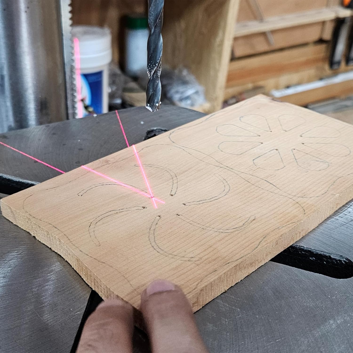
Image 5.3: The laser precision feature in action, showing crosshairs projected onto a wooden workpiece to guide the drill bit.
5.5 Drilling Procedure
- Select Bit: Choose the appropriate drill bit for your material and desired hole size. Insert it into the chuck and tighten securely with the chuck key.
- Adjust Speed: Set the drill press to the recommended RPM for your material.
- Position Workpiece: Place the workpiece on the worktable. Use clamps or a drill press vise to secure it firmly. Never hold the workpiece by hand.
- Adjust Table/Depth: Adjust the worktable height and tilt as needed. Set the drilling depth using the depth adjustment guide.
- Align Laser: Use the laser to align the drill bit with your marked drilling point.
- Start Drilling: Turn on the drill press. Slowly lower the drill bit into the workpiece using the feed handle. Apply steady, even pressure.
- Clear Chips: Periodically raise the bit to clear chips, especially when drilling deep holes in metal.
- Finish: Once the desired depth is reached, raise the bit completely and turn off the drill press.

Image 5.4: The depth and table adjustment guide, allowing for precise control over drilling depth and table positioning.
6. Maintenance
Regular maintenance ensures the longevity and safe operation of your drill press.
- Cleaning: After each use, clean the drill press to remove dust, chips, and debris. Use a brush or vacuum; never use compressed air directly on electrical components.
- Lubrication: Periodically apply a light coat of machine oil to moving parts such as the column, quill, and table adjustment mechanisms to prevent rust and ensure smooth operation.
- Chuck Care: Keep the chuck jaws clean and free of debris. If the chuck becomes stiff, clean it thoroughly and apply a small amount of lubricant.
- Belt Tension (if applicable): Check belt tension periodically. Refer to the pulley cover diagram for guidance on belt adjustment if your model uses a belt drive system.
- Electrical Inspection: Regularly inspect the power cord and plug for any damage. Do not operate the machine with a damaged cord.
7. Troubleshooting
Refer to this section for common issues and their potential solutions.
| Problem | Possible Cause | Solution |
|---|---|---|
| Drill press does not start | No power supply; Emergency stop engaged; Faulty switch | Check power connection; Reset emergency stop button; Contact customer support if switch is faulty |
| Excessive vibration or noise | Loose components; Unbalanced drill bit; Worn bearings | Check all fasteners; Ensure drill bit is properly seated and not bent; Contact customer support for bearing issues |
| Inaccurate drilling | Workpiece not clamped; Loose chuck; Laser misalignment | Secure workpiece firmly; Retighten chuck; Calibrate laser if adjustable (refer to specific instructions if available) |
| Motor overheats | Overloading; Insufficient ventilation | Reduce load; Ensure proper airflow around motor; Allow motor to cool down |
8. Warranty and Support
BUCKTOOL provides a 2-year limited warranty for this product. This warranty covers defects in materials and workmanship under normal use.
For any inquiries, technical assistance, or warranty claims, please do not hesitate to contact BUCKTOOL customer service. Please have your model number (B0F9KCM88L) and purchase date available when contacting support.
We are committed to offering the best customer service possible.