1. Introduction
This manual provides essential information for the safe and effective installation, operation, and maintenance of the perdnmkg PFM710-C6-B-M Flow Switch. Please read this manual thoroughly before using the product and retain it for future reference.
2. Safety Information
WARNING: Failure to follow these safety instructions may result in personal injury, product damage, or system malfunction.
- Ensure all power is disconnected before installation, maintenance, or troubleshooting.
- Installation and wiring should only be performed by qualified personnel in accordance with local electrical codes and regulations.
- Do not exceed the specified maximum pressure or flow rate for the device.
- Verify correct voltage and current ratings before connecting the power supply.
- Protect the device from physical impact, excessive vibration, and extreme temperatures.
- Ensure proper sealing of all connections to prevent leaks.
3. Product Overview
The perdnmkg PFM710-C6-B-M is a compact flow switch designed for monitoring fluid flow within industrial and scientific applications. It provides reliable flow detection and output signals for system control.
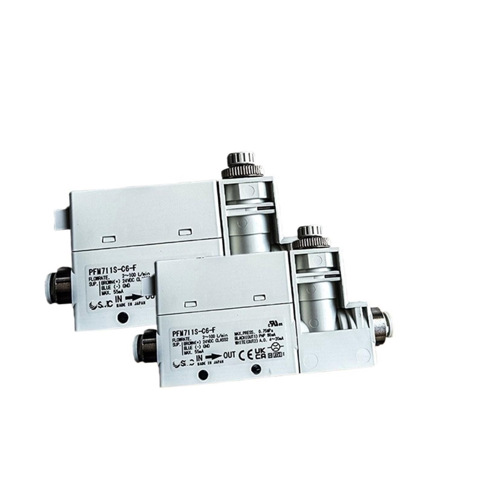
Figure 1: perdnmkg PFM Series Flow Switches. These devices are designed for precise flow monitoring in various industrial settings.
Key Features (Typical for PFM Series)
- Flowrate Range: 2 to 100 L/min
- Supply Voltage: 24VDC (Brown wire for positive, Blue wire for ground)
- Maximum Current Consumption: 55mA
- Maximum Pressure: 0.75 MPa
- Output 1: PNP, 80mA (Black wire)
- Output 2: Analog Output (A.O.), 4-20mA (White wire)
4. Setup and Installation
4.1 Mounting
Mount the flow switch securely in the desired position within the fluid line. Ensure the 'IN' and 'OUT' ports are correctly aligned with the direction of flow. Avoid mounting in locations subject to excessive vibration or direct impact.
4.2 Fluid Connections
Connect the fluid inlet to the port marked 'IN' and the fluid outlet to the port marked 'OUT'. Use appropriate fittings and ensure all connections are leak-tight. Refer to the product specifications for compatible pipe sizes.
4.3 Electrical Connections
Connect the flow switch to a stable 24VDC power supply according to the following wiring diagram:
- Brown Wire: +24VDC Supply
- Blue Wire: 0V (Ground)
- Black Wire (OUT1): PNP Output (Digital signal for flow detection)
- White Wire (OUT2): Analog Output (4-20mA signal proportional to flow rate)
Ensure all electrical connections are insulated and protected from environmental factors.
5. Operating Instructions
Once installed and powered, the flow switch will begin monitoring the fluid flow. The device provides two types of output signals:
- Digital Output (PNP): This output changes state (e.g., ON/OFF) when the flow rate crosses a pre-set threshold. Refer to your system's control logic for interpreting this signal.
- Analog Output (4-20mA): This output provides a continuous current signal that is proportional to the measured flow rate. A 4mA signal typically indicates zero flow, while a 20mA signal indicates the maximum flow rate within the device's range. This signal can be used for precise flow measurement and control.
Monitor the output signals using appropriate control systems or measurement devices to ensure proper operation and to detect any deviations from desired flow conditions.
6. Maintenance
Regular maintenance ensures the longevity and accuracy of the flow switch.
- Periodic Inspection: Visually inspect the device and connections for any signs of damage, corrosion, or leaks.
- Cleaning: If necessary, gently clean the exterior of the device with a soft, damp cloth. Do not use abrasive cleaners or solvents.
- Calibration Check: Periodically verify the accuracy of the flow switch's readings against a known standard, if applicable to your application.
- Fluid Quality: Ensure the fluid being monitored is free from excessive particulate matter that could clog or damage the sensor.
7. Troubleshooting
If you encounter issues with your flow switch, refer to the following table:
| Problem | Possible Cause | Solution |
|---|---|---|
| No output signal | No power supply Incorrect wiring Sensor malfunction | Check power connections and voltage Verify wiring against Section 4.3 Contact support if power and wiring are correct |
| Inaccurate flow reading (Analog Output) | Air bubbles in fluid Sensor contamination Incorrect calibration | Ensure fluid line is free of air Inspect and clean sensor if accessible Perform calibration check |
| No flow detection (Digital Output) | Flow rate below threshold Obstruction in flow path Sensor malfunction | Verify actual flow rate Check for blockages in the fluid line Contact support |
| Leaks at connections | Loose fittings Damaged seals | Tighten fittings appropriately Replace seals or fittings as needed |
If troubleshooting steps do not resolve the issue, please contact perdnmkg customer support.
8. Specifications
| Attribute | Value |
|---|---|
| Model Number | PFM710-C6-B-M |
| Manufacturer | perdnmkg |
| Part Number | perdnmkg |
| Item Weight | 1.76 ounces |
| Package Dimensions | 0.39 x 0.39 x 0.39 inches |
| Flowrate Range (Typical) | 2 - 100 L/min |
| Supply Voltage (Typical) | 24VDC |
| Max Current Consumption (Typical) | 55mA |
| Max Pressure (Typical) | 0.75 MPa |
| Digital Output (Typical) | PNP, 80mA |
| Analog Output (Typical) | 4-20mA |
| ASIN | B0F9JBJBB4 |
| Date First Available | May 22, 2025 |
9. Warranty and Support
For warranty information, please refer to the documentation provided with your purchase or contact the seller directly. For technical support or further assistance, please reach out to perdnmkg customer service through their official channels.