
1. Introduction
The Generic ATS220 is an advanced Automatic Transfer Switch (ATS) controller designed to intelligently monitor and manage dual power sources for generator systems. It ensures a continuous and reliable power supply by automatically switching between the main power grid and a backup generator in the event of a power failure or fluctuation. Featuring a clear LCD display and robust protection systems, the ATS220 is suitable for a wide range of industrial, residential, and commercial applications.
This manual provides essential information for the safe installation, operation, and maintenance of your ATS220 controller.
2. Safety Information
Please read and understand all safety instructions before installing or operating the ATS220 controller. Failure to follow these instructions may result in electric shock, fire, serious injury, or property damage.
- Qualified Personnel Only: Installation and maintenance should only be performed by qualified electricians or service personnel familiar with electrical systems and generator operation.
- Disconnect Power: Always disconnect all power sources (main utility and generator) before performing any installation, wiring, or maintenance on the ATS220 controller or associated equipment.
- Proper Grounding: Ensure the controller and all connected equipment are properly grounded according to local electrical codes.
- Environmental Conditions: Do not expose the controller to excessive moisture, dust, or extreme temperatures. Operate within specified environmental limits.
- Inspect for Damage: Before installation, inspect the unit for any signs of physical damage. Do not install a damaged unit.
3. Product Overview
The ATS220 controller features a compact design with an intuitive front panel for easy monitoring and control. The LCD display provides real-time information on voltage, frequency, and amperage, while dedicated buttons allow for manual operation and parameter adjustments.
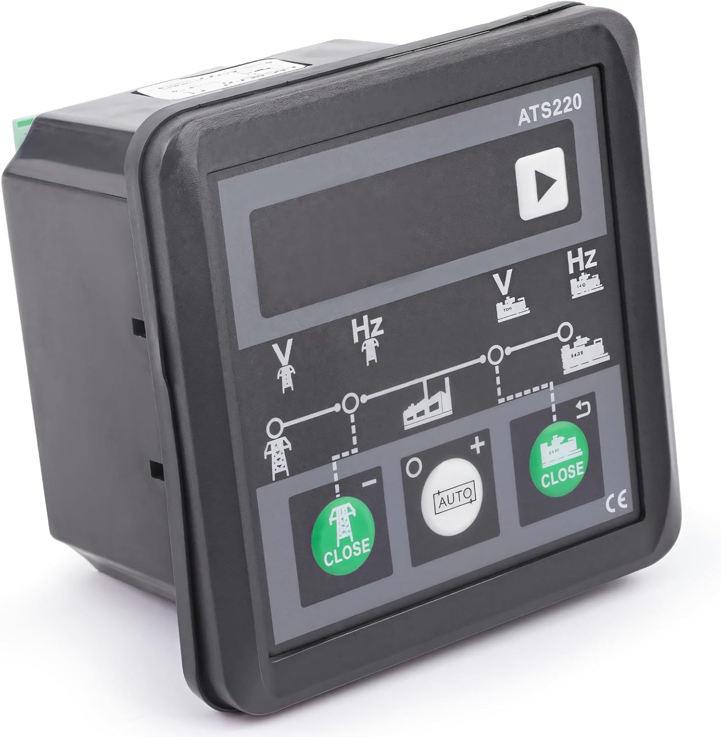
Figure 3.1: Front view of the ATS220 Automatic Transfer Switch Controller. This image shows the main display, control buttons for 'CLOSE' (generator and mains), and 'AUTO' mode selection.
The rear panel houses the necessary connection terminals for power inputs, generator start/stop signals, and load outputs. These terminals are clearly labeled for straightforward wiring.

Figure 3.2: Detailed view of the ATS220 controller's wiring terminals. This image highlights the connection points for remote start, generator AC input, and main AC input, along with internal circuitry.
4. Installation
4.1. Unpacking and Inspection
Carefully unpack the ATS220 controller and all included components. Verify that all items listed in the 'What's in the Box' section (Section 7) are present and undamaged. If any items are missing or damaged, contact your supplier immediately.

Figure 4.1: Contents of the ATS220 product package. This image displays the ATS220 controller alongside a bundle of multi-colored wiring harnesses, indicating a complete setup package.
4.2. Mounting
The ATS220 controller is designed for panel mounting. Choose a location that is easily accessible, free from excessive vibration, moisture, and direct sunlight. Ensure adequate ventilation around the unit.
- Refer to the product dimensions for precise cutout requirements.
- Secure the controller using the provided mounting hardware.

Figure 4.2: Dimensions of the ATS220 Automatic Transfer Switch Controller. This image provides measurements for the controller's height (3.01"), width (3.01"), and depth (2.02"), essential for proper panel mounting.
4.3. Wiring
All wiring must comply with local and national electrical codes. Use appropriate wire gauges for the current ratings. Refer to the wiring diagram provided with the controller for specific connections. A general overview of connections includes:
- Main Utility Power Input: Connect the primary power source (e.g., grid power) to the designated terminals.
- Generator Power Input: Connect the backup generator power output to its respective terminals.
- Load Output: Connect the controlled load to these terminals.
- Generator Start/Stop Signals: Connect the control signals to initiate and stop the generator.
- Remote Monitoring/Control (if applicable): Connect any remote communication lines.
Ensure all connections are secure and properly insulated. Double-check all wiring before applying power.

Figure 4.3: ATS220 controller installed on a generator frame. This image demonstrates a typical installation scenario, showing the controller mounted within a protective enclosure on a generator.
5. Operation
5.1. Initial Power-Up
Once installation and wiring are complete and verified, apply power to the ATS220 controller. The LCD display will illuminate, showing initial system status.
5.2. LCD Display
The clear LCD interface provides real-time monitoring of critical parameters:
- Voltage (V): Displays the voltage of both main utility and generator power sources.
- Frequency (Hz): Shows the frequency of both power sources.
- Amperage (A): Indicates the current draw on the load.
- Status Indicators: Icons or text will show which power source is active, fault conditions, and operational mode.
5.3. Operating Modes
The ATS220 typically operates in two main modes:
- Automatic Mode (AUTO button): In this mode, the controller continuously monitors both power sources. If the main utility power fails or falls outside acceptable parameters, the controller will automatically start the generator, transfer the load, and then switch back to utility power when it is restored and stable.
- Manual Mode (CLOSE buttons): Allows for manual control of the transfer switch. Users can manually close the main utility contactor or the generator contactor using the respective 'CLOSE' buttons. This mode is typically used for testing or specific operational requirements.
5.4. Parameter Adjustment
The ATS220 allows for adjustment of various operational parameters to suit different power setups and user preferences. These may include:
- Voltage and frequency thresholds for transfer.
- Time delays for generator start, transfer, and cool-down.
- Engine crank and rest times for generator starting.
Refer to the detailed programming guide (if provided separately) for instructions on accessing and modifying these parameters.
6. Maintenance
Regular maintenance ensures the longevity and reliable operation of your ATS220 controller.
- Cleaning: Keep the controller's exterior clean and free of dust. Use a soft, dry cloth. Do not use abrasive cleaners or solvents.
- Connection Checks: Periodically inspect all wiring connections for tightness and signs of corrosion. Loose connections can lead to intermittent operation or damage.
- Environmental Inspection: Ensure the operating environment remains within specified conditions (temperature, humidity).
- Functional Testing: It is recommended to periodically test the automatic transfer function by simulating a utility power failure to ensure the generator starts and the load transfers correctly.
7. Troubleshooting
The ATS220 incorporates an advanced protection system with intelligent fault detection. If an issue arises, the LCD display may show error codes or status messages.
- No Display/Power: Check the power supply to the controller and ensure all connections are secure.
- Generator Fails to Start: Verify the generator's fuel level, battery charge, and general operational status. Check the generator start/stop wiring from the ATS220.
- Load Not Transferring: Ensure both utility and generator power sources are stable and within acceptable parameters. Check the contactor wiring.
- Under/Over Voltage or Frequency Errors: The controller will safeguard against these conditions. Check the incoming power quality from both sources. If persistent, consult an electrician.
- Phase Sequence Issues: For three-phase systems, incorrect phase sequence will trigger a fault. Verify phase connections.
For complex issues or persistent faults, consult a qualified technician or contact customer support.
8. Specifications
| Feature | Specification |
|---|---|
| Model | ATS220 |
| Product Dimensions | 6.89 x 3.74 x 4.53 inches |
| Item Weight | 12.3 ounces |
| Color | Black |
| Manufacturer | Generic |
| Display Features | LCD, Wireless (refers to display communication, not power transfer) |
| ASIN | B0F9FDJWC3 |
9. What's in the Box
The ATS220 package typically includes the following components:
- ATS220 Automatic Transfer Switch Controller
- Mounting Hardware
- Wiring Harness
- User Guide (this document)
10. Warranty and Support
For warranty information, technical support, or service inquiries, please refer to the documentation provided with your purchase or contact the retailer/manufacturer directly. Keep your purchase receipt as proof of purchase.