
mGYDY 30A Electric Motor Controller+LCD8HUP Display+TT009 Thumb Throttle+1 T 5 Cable+KT-V12 PAS
mGYDY 36-48V 1000W KT 30A Electric Bicycle Brushless Motor Controller Kit User Manual
Model: 30A Electric Motor Controller+LCD8HUP Display+TT009 Thumb Throttle+1 T 5 Cable+KT-V12 PAS
1. Introduction
This manual provides instructions for the installation, operation, and maintenance of the mGYDY 36-48V 1000W KT 30A Electric Bicycle Brushless Motor Controller Kit. This kit is designed to provide steady speed control and sensitive braking response for 1000W e-bike motors, enhancing your electric bicycle experience. Please read this manual thoroughly before installation and use to ensure proper function and safety.
2. Package Contents
The mGYDY Electric Bicycle Brushless Motor Controller Kit includes the following components:
- 1x 36V/48V 30A Brushless Motor Controller
- 1x LCD8HUP Controller Display Panel
- 1x TT009 Thumb Throttle
- 1x 1T5 Cable (Main wiring harness)
- 1x KT-V12 Pedal Assist Sensor (PAS)
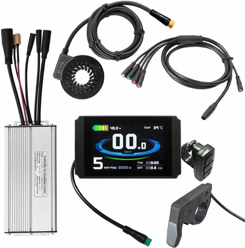
This image displays all the components of the kit: the brushless motor controller, LCD8HUP display, TT009 thumb throttle, 1T5 cable, and KT-V12 PAS sensor.
2.1. Brushless Motor Controller
The controller manages power delivery to the motor and processes signals from the display, throttle, and PAS. It features an aluminum alloy shell for efficient heat dissipation.

This image illustrates the physical dimensions and various connection points on the controller, including the lamp line, assisted magnetic point, 1T5 cable, electric machine (motor), and power source (XT60).
2.2. LCD8HUP Display Panel
The LCD8HUP display provides real-time information such as speed, battery level, temperature, and trip distance. It is equipped with a waterproof plug and a USB charging socket.

This image shows the physical size of the display (11cm x 7cm) and highlights its waterproof plug, 230mm line length, compatibility with 24V/36V/48V systems, black color, and 300g weight.

This image demonstrates the USB charge socket on the LCD8HUP display, which provides a 5V 500mA output for charging mobile devices.
2.3. TT009 Thumb Throttle
The TT009 thumb throttle allows for manual speed control of the electric motor.

This image details the TT009 Thumb Throttle's specifications, including its type (Quick Thumb Throttle), material (PC+ABS), weight (approx. 26g), usage (Mountain Bikes/Road Bicycles), voltage compatibility (12V-72V), plug type (3pin SM Plug/WP Plug), color (Black), cable length (180cm SM, 25cm WP), and installation side (Right and Left).
2.4. 1T5 Cable
The 1T5 cable is the main wiring harness that connects the controller to the display, throttle, and brake sensors.

This image provides information about the 1T5 cable, showing its 9-pin controller connector, 2-pin lamp line, 3-pin dial handle, 5-pin appearance, and two 2-pin brake connectors. It also notes that the 2-core waterproof plug is for brake connections.
3. Technical Specifications
| Feature | Specification |
|---|---|
| Product Name | 36V/48V 30A E-bike Brushless Controller 1000W for KT Parts with 1T5 Cable |
| Rated Voltage | 36V/48V |
| Rated Current | 15A |
| Rated Power | 1000W |
| Low Pressure Protection | DC30/40 ± 0.5V |
| Speed Setting | 1-4.2V |
| Brake Input | Low Level |
| Controller Material | Aluminum alloy |
| Controller Dimensions | 170x80x41mm |
| Display Type | KT-LCD8HU Display |
| Display Voltage Compatibility | 24V/36V/48V |
| Display Weight | 300g |
| Throttle Type | Quick Thumb Throttle (TT009) |
| Throttle Material | PC+ABS |
| Throttle Weight | Approx. 26g |
| Throttle Voltage Compatibility | 12V-72V |
| Cable Type | 1T5 Cable |
| Color | Silver/Black |
4. Installation Guide
Proper installation is crucial for the safe and efficient operation of your e-bike kit. It is recommended that installation be performed by an experienced technician if you are unfamiliar with e-bike conversions.
4.1. General Connection Overview
The controller acts as the central hub for all electrical components. Ensure all connections are secure and correctly oriented. The kit utilizes waterproof plugs for enhanced durability.

This image shows the KT 30A fully waterproof controller connected to the 1T5 cable. It highlights the XT60 plug for power, LED cable, and 1000W motor connection.
4.2. Controller Mounting
- Select a secure location on your bicycle frame, away from moving parts and potential impact zones.
- Ensure adequate airflow around the controller for optimal heat dissipation.
- Mount the controller using appropriate fasteners (not included) to prevent movement during operation.
4.3. Wiring Connections
Connect the components to the controller using the provided 1T5 cable and individual connectors. Refer to the diagrams below for specific connections.
- Motor Connection: Connect the motor's 9-pin waterproof plug to the corresponding port on the controller. This 30A controller is typically suitable for 1000W motors.
- Power Connection: Connect your battery (36V/48V) to the XT60 power input on the controller.
- 1T5 Cable Connection: Plug the 1T5 cable into the designated port on the controller. This cable branches out to connect the display, throttle, and brake sensors.
- LCD8HUP Display: Connect the display to the 1T5 cable's display connector. The controller must be used with a KT series display.
- TT009 Thumb Throttle: Connect the thumb throttle to its designated connector on the 1T5 cable.
- Brake Sensors: Connect your e-bike's brake sensors to the 2-pin brake connectors on the 1T5 cable.
- KT-V12 PAS Sensor: Install the PAS sensor on your bicycle's crank arm and connect it to the controller's PAS input.
- Light Wire: If applicable, connect your e-bike's light to the dedicated light wire from the controller.

This image provides a close-up of the controller's connection area, showing the large 9-core motor plug (18.8mm diameter) and the 1T5 cable connection. It confirms the 30A controller's suitability for 1000W motors.
5. Operation
5.1. Powering On/Off
- Ensure all connections are secure and the battery is charged.
- Press and hold the power button on the LCD8HUP display to turn on the system.
- To power off, press and hold the power button again.
5.2. LCD8HUP Display Functions
The display provides various metrics and allows for system configuration. Consult the specific LCD8HUP display manual for detailed instructions on navigating menus and adjusting settings.
- Speed Indication: Displays current speed (Km/h or Mph).
- Battery Level: Shows remaining battery charge.
- Trip Information: Displays trip distance, total distance, and ride time.
- Motor Power: Indicates real-time motor power output.
- Temperature: Shows system temperature.
- USB Charging: The display features a USB port (5V 500mA) for charging external devices.
5.3. Speed Control (Throttle and PAS)
- Thumb Throttle (TT009): Use the thumb throttle to manually control the motor's speed. Apply gentle pressure for smooth acceleration.
- Pedal Assist System (KT-V12 PAS): The PAS sensor detects pedaling motion and provides motor assistance based on the selected assist level on the display.
6. Maintenance
- Regular Inspection: Periodically check all cables and connectors for signs of wear, damage, or loose connections.
- Cleaning: Keep the controller, display, and other components clean. Use a soft, damp cloth. Avoid harsh chemicals or abrasive materials.
- Heat Dissipation: Ensure the controller's aluminum alloy shell remains clear of obstructions to allow for proper heat dissipation.
- Water Exposure: While components are waterproof, avoid prolonged submersion or high-pressure washing directly on electrical parts.
- Storage: When not in use for extended periods, store the e-bike in a dry, temperate environment.
7. Troubleshooting
| Problem | Possible Cause | Solution |
|---|---|---|
| System does not power on. | Loose battery connection, discharged battery, faulty display connection. | Check battery connection and charge level. Ensure display cable is securely connected to the 1T5 cable and controller. |
| Motor not assisting or no power. | Loose motor cable, PAS sensor issue, throttle issue, incorrect display settings. | Verify motor cable connection. Check PAS sensor installation and connection. Test throttle functionality. Ensure correct assist level is selected on the display. |
| Display shows error code. | Specific component malfunction or communication error. | Refer to the LCD8HUP display manual for a list of error codes and their corresponding solutions. Check relevant connections. |
| Inconsistent speed control. | Throttle malfunction, PAS sensor interference, loose connections. | Inspect throttle for damage. Ensure PAS sensor is clean and correctly aligned. Check all wiring connections. |
If problems persist after attempting these solutions, please contact customer support.
8. Warranty Information
This mGYDY product is covered by a 1-Year Manufacturer Warranty from the date of purchase. This warranty covers defects in materials and workmanship under normal use. It does not cover damage resulting from misuse, accidents, unauthorized modifications, or improper installation.
Please retain your proof of purchase for warranty claims.
9. Customer Support
For technical assistance, troubleshooting beyond this manual, or warranty inquiries, please contact your retailer or the manufacturer directly. Provide your product model number and proof of purchase when seeking support.
Manufacturer: mGYDY
Related Documents - 30A Electric Motor Controller+LCD8HUP Display+TT009 Thumb Throttle+1 T 5 Cable+KT-V12 PAS
 |
E-bike Controller Wiring Guide: 1000W-2000W Sine Wave Controller Connector Identification Detailed wiring diagram and connector identification for a 1000W-2000W 30A/40A sine wave e-bike controller. Covers motor cables, power, LCD display, throttle, electronic brake, PAS, and lights, with a visual guide to the cable harness. |
 |
EZKT S966 Electric Bicycle Controller and Display Instruction Manual Instruction manual for the EZKT S966 electric bicycle controller and display series, covering warnings, product details, installation, precautions, functions, common problems, and specifications for 17A, 26A, and 30A controllers. |
 |
Electric Bicycle Controller and Display Instruction Manual Instruction manual for the E-Bike JN Controller & Display Series, providing details on warnings, product specifications, installation, usage, precautions, functions, common problems, and after-sales service for electric bicycle controllers and H100 displays. |
 |
Electric Bicycle Controller & Display Instruction Manual - E-Bike JN Instruction manual for the E-Bike JN electric bicycle controller and S866 display series. Covers installation, precautions, functions, common problems, and specifications for 15A, 17A, 22A, and 30A controllers. |
 |
Electric Bicycle Controller and Display Instruction Manual Instruction manual for E-Bike JN Controller & Display series, detailing specifications, installation, precautions, and troubleshooting for electric bicycle controllers and displays. |
 |
Ophir Thermal Sensor Accessories: Fiberoptic and Other Adapters Explore Ophir's range of accessories for thermal sensors, including fiberoptic adapters (SC, ST, FC, SMA) and other essential components like protective housings, scatter shields, and stands. Find part numbers and compatibility information for various sensor models. |
Ask a question about this manual
Ask about setup, troubleshooting, compatibility, parts, safety, or missing instructions. Manuals+ will review the question and use this page’s manual context to help answer it.