1. Introduction
This manual provides detailed instructions for the installation, setup, and operation of your Yoidesu H81 M-ATX LGA 1150 Motherboard. Please read this manual thoroughly before beginning installation to ensure proper setup and to maximize the performance and longevity of your system. This motherboard is designed for desktop personal computers, supporting Intel 4th generation Core i3, i5, i7, E3 V3 series, Celeron G series, and G series 22nm CPU processors.
2. Package Contents
Upon opening the package, please verify that all items are present and in good condition. If any items are missing or damaged, contact your retailer immediately.
- 1 x Yoidesu H81 M-ATX LGA 1150 Motherboard
- (Additional accessories such as SATA cables, I/O shield, and driver CD may be included depending on the specific retail package. Please check your packaging.)
3. Motherboard Layout and Components
Familiarize yourself with the various components and connectors on your motherboard. This section provides an overview of the key areas.

Figure 3.1: Front view of the Yoidesu H81 M-ATX LGA 1150 Motherboard, showing the CPU socket, RAM slots, and various connectors.

Figure 3.2: Rear view of the Yoidesu H81 M-ATX LGA 1150 Motherboard, illustrating the mounting points and the underside of the CPU socket area.
3.1 Key Features Overview
- CPU Socket: LGA 1150, supporting Intel 4th generation Core i3/i5/i7, E3 V3 series, Celeron G series, and G series 22nm processors.
- Memory Slots: Two 240-pin DDR3 SDRAM slots, supporting up to 16GB total memory in a dual-channel architecture. Compatible with DDR3 1066/1333/1600 MHz modules.
- Storage Interfaces: One Serial ATA 3.0 (6GB/s) port and two Serial ATA 2.0 (3GB/s) ports for traditional storage devices.
- M.2 Interface: A high-speed M.2 slot with jumpers, supporting both NVMe and NGFF modes for modern solid-state drives.
- Expansion Slots: One PCI Express x16 slot for graphics cards and one PCI Express x1 slot for other expansion cards.
- Integrated Graphics Output: VGA and HDMI ports for 1080P video output, requiring a CPU with integrated graphics.
- Networking: Onboard Realtek 10/100 Mbps LAN for network connectivity.
- Audio: Onboard Realtek ALC 6-channel HD sound codec with front sound and microphone interfaces.
- USB Ports: Four USB 2.0 ports and two USB 3.0 ports for peripheral connectivity.
- Power Connectors: One 24-pin ATX power port and one 4-pin ATX 12V power port.
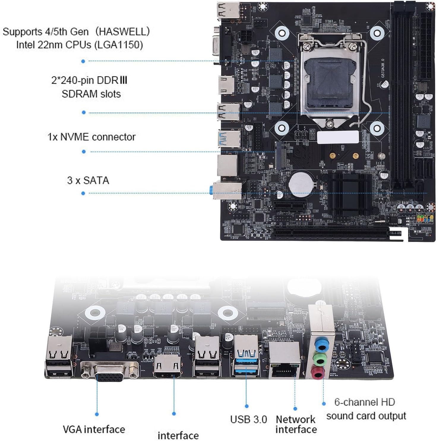
Figure 3.3: Diagram illustrating the location of key components including the CPU socket, DDR3 RAM slots, NVMe connector, SATA ports, VGA interface, USB 3.0, Network interface, and 6-channel HD sound output.
4. Specifications
| Feature | Description |
|---|---|
| Model | H81 |
| Form Factor | M-ATX (17 x 19 cm / 6.7 x 7.5 inches) |
| CPU Socket | LGA 1150 |
| Supported CPUs | Intel Core i3/i5/i7 4th generation, E3 V3 series, Celeron G series, G series 22nm processors |
| Chipset | Intel H81 |
| Memory Slots | 2 x 240-pin DDR3 SDRAM |
| Memory Type | DDR3 1066/1333/1600 MHz, Unbuffered, Dual Channel |
| Max Memory Capacity | 16GB |
| Storage Ports | 1 x SATA 3.0 (6GB/s), 2 x SATA 2.0 (3GB/s) |
| M.2 Interface | 1 x M.2 slot (supports NVMe and NGFF modes) |
| PCIe Expansion Slots | 1 x PCI Express x16, 1 x PCI Express x1 |
| Integrated LAN | Realtek 10/100 Mbps |
| Integrated Audio | Realtek ALC 6-channel HD Audio Codec |
| Rear I/O Ports | 4 x USB 2.0, 2 x USB 3.0, 1 x VGA, 1 x HDMI, 1 x RJ45, 1 x 3-in-1 Audio (Line In/Out, Mic In) |
| Internal I/O Connectors | 24-pin ATX Power, 4-pin ATX 12V Power, Front Panel Audio, Front Panel USB, etc. |
| Battery | CR2032 (Built-in) 240mAh |
| PCB Design | 8-layer PCB, 6-phase power design, All solid capacitors |
5. Setup and Installation
Follow these steps carefully to install your motherboard and its components into your computer case.
5.1 CPU Installation
Handle the CPU with extreme care. Do not touch the CPU contacts or the pins in the socket.

Figure 5.1: Step-by-step guide for installing an LGA 1150 CPU onto the motherboard. This includes pressing down and lifting the lever, opening the CPU cover, aligning the CPU with the socket's triangle symbols, removing the plastic cover, and securing the CPU by lowering the lever into the groove. Important considerations about not touching CPU contacts or pins are also shown.
- Prepare the Socket: Press down on the CPU socket lever and lift it to open the CPU cover.
- Align the CPU: Carefully align the triangle symbol on the CPU with the corresponding triangle on the CPU socket. Gently place the CPU into the socket without forcing it.
- Secure the CPU: Lower the CPU cover and then press down the lever until it clicks into place, securing the CPU.
- Install CPU Cooler: Apply thermal paste (if not pre-applied to cooler) and install your CPU cooler according to its manufacturer's instructions.
5.2 Memory (RAM) Installation
This motherboard supports DDR3 memory modules. Ensure you use compatible RAM.

Figure 5.2: Close-up view of the two 240-pin DDR3 SDRAM memory slots on the Yoidesu H81 motherboard, highlighting their location for memory module installation.
- Open Clips: Open the retention clips at both ends of the DIMM slot.
- Align Module: Align the notch on the DDR3 memory module with the key in the DIMM slot.
- Insert Module: Press down firmly on both ends of the memory module until the retention clips snap into place.
5.3 Storage Device Installation (M.2 / SATA)
Install your M.2 SSDs and SATA hard drives/SSDs.

Figure 5.3: View of the high-speed M.2 interface on the Yoidesu H81 motherboard, indicating its support for both NVMe and NGFF drives via jumpers.
- M.2 SSD: Insert the M.2 SSD into the M.2 slot at an angle, then gently push it down and secure it with the provided screw. Ensure jumpers are set correctly for NVMe or NGFF mode as per your SSD type.
- SATA Devices: Connect SATA data cables from your storage devices (HDD/SSD) to the SATA 3.0 (6GB/s) or SATA 2.0 (3GB/s) ports on the motherboard. Connect SATA power cables from your power supply to the devices.
5.4 Connecting Peripherals and Power
Connect your power supply, graphics card (if applicable), and other peripherals.
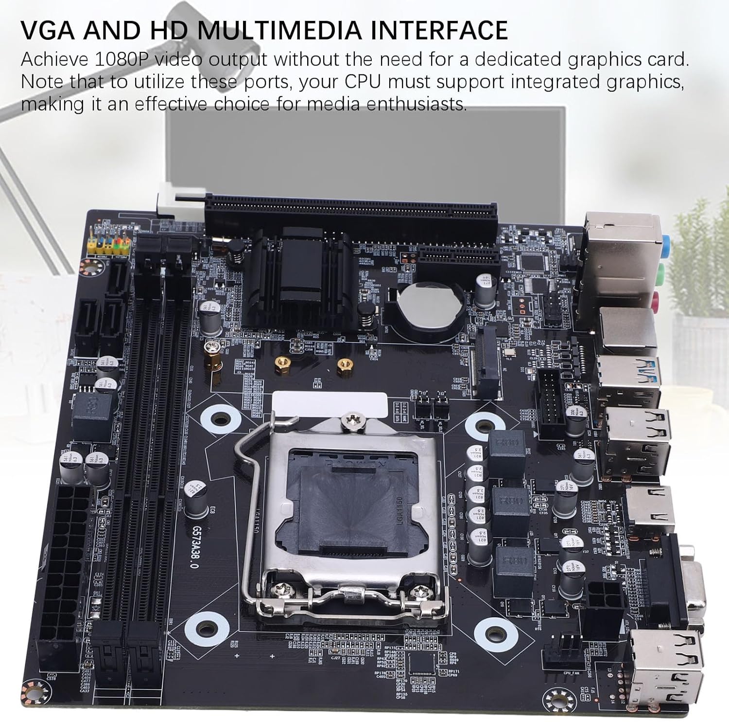
Figure 5.4: The VGA and HDMI video output ports on the Yoidesu H81 motherboard, which provide 1080P video output when used with a CPU that has integrated graphics.
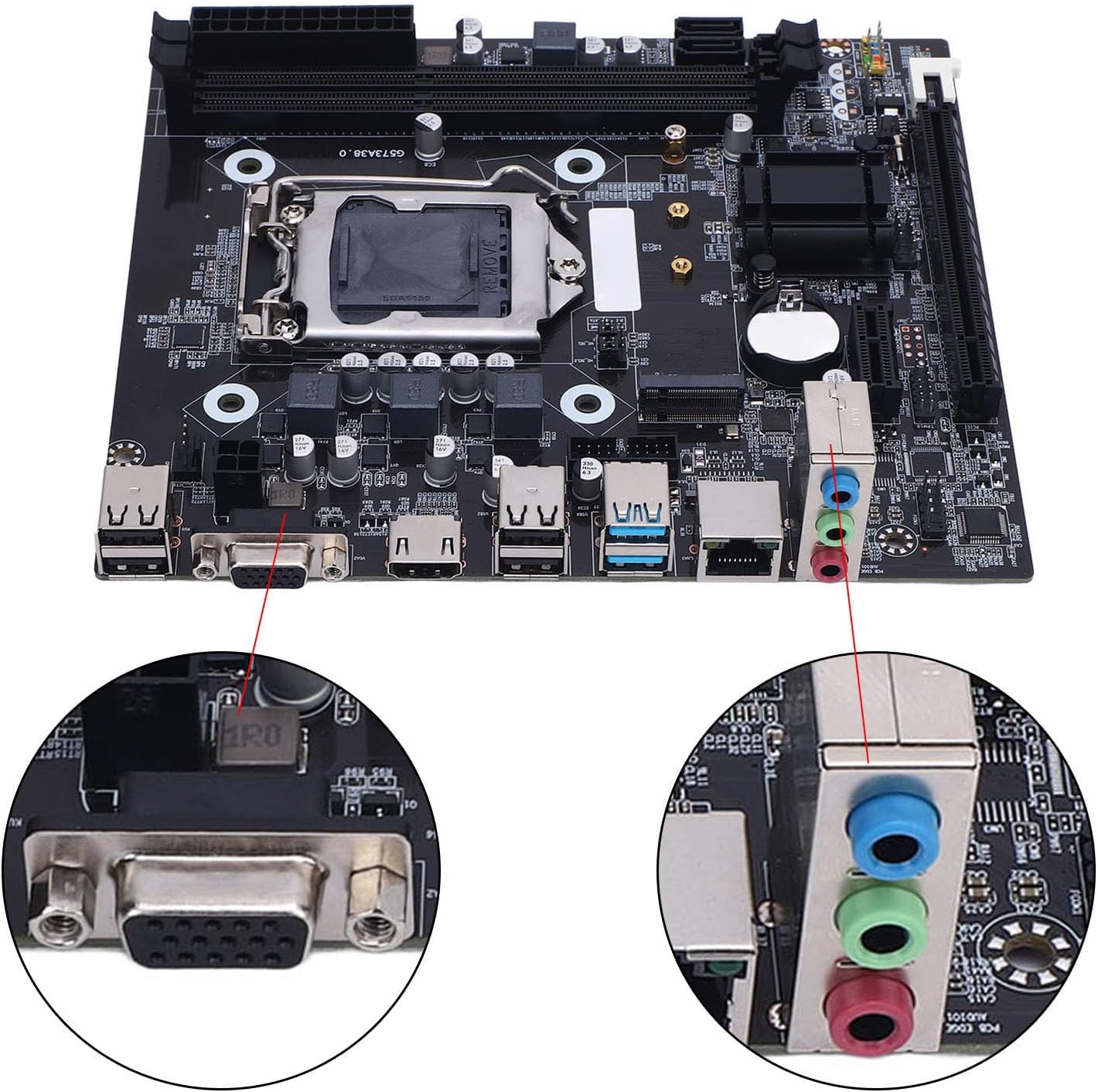
Figure 5.5: A close-up view of the rear I/O panel of the Yoidesu H81 motherboard, highlighting the VGA port and the 3-in-1 audio jacks (green for line out, blue for line in, pink for microphone in).
- Power Supply: Connect the 24-pin ATX power connector and the 4-pin ATX 12V power connector from your power supply to the corresponding ports on the motherboard.
- Graphics Card: If using a dedicated graphics card, install it into the PCI Express x16 slot and connect any necessary PCIe power cables from your power supply.
- Front Panel Connectors: Connect the front panel USB, audio, power switch, reset switch, and LED connectors from your computer case to the appropriate headers on the motherboard. Refer to your case manual for specific pin assignments.
- Rear I/O: Connect your monitor to the VGA or HDMI port (if using integrated graphics), and connect USB devices, Ethernet cable, and audio devices to the rear I/O ports.
6. Operating Instructions
6.1 First Boot and BIOS Setup
- Power On: After all components are installed and connected, power on your system.
- Access BIOS: During startup, repeatedly press the DEL or F2 key (common keys, consult screen prompts if different) to enter the BIOS/UEFI setup utility.
- Configure Settings: In the BIOS, you can configure boot order, system time, and other advanced settings. Save changes and exit to continue booting into your operating system installer.
6.2 Driver Installation
After installing your operating system, install the necessary drivers for the motherboard components. These typically include chipset drivers, LAN drivers, and audio drivers. Drivers can usually be found on the Yoidesu support website or on a driver CD included with your motherboard (if applicable).
7. Maintenance
- Keep Clean: Regularly clean your computer case and motherboard to prevent dust buildup, which can lead to overheating and component failure. Use compressed air to gently remove dust.
- BIOS Updates: Periodically check the Yoidesu support website for BIOS updates. BIOS updates can improve system stability, compatibility, and performance. Follow the update instructions carefully to avoid damaging the motherboard.
- Component Checks: Ensure all cables are securely connected and components are properly seated.
8. Troubleshooting
This section addresses common issues you might encounter.
- No Power:
- Check if the power supply is connected correctly to the motherboard (24-pin and 4-pin ATX).
- Ensure the power supply switch is in the 'ON' position.
- Verify that the front panel power switch cable is correctly connected to the motherboard header.
- No Display:
- Ensure your monitor is connected to the correct video output port (VGA or HDMI on the motherboard, or on your dedicated graphics card).
- Verify that your CPU has integrated graphics if you are using the motherboard's video outputs.
- Reseat the RAM modules. Incorrectly seated RAM is a common cause of no display.
- If using a dedicated graphics card, reseat it in the PCIe slot and ensure its power cables are connected.
- System Instability / Crashes:
- Check for overheating. Ensure CPU cooler is properly installed and case fans are functioning.
- Run memory diagnostic tools to check for faulty RAM.
- Ensure all drivers are up to date.
- Check power supply wattage; it might be insufficient for your components.
- Operating System Not Booting:
- Check boot order in BIOS to ensure your primary storage device is selected.
- Verify that your operating system is correctly installed on the storage device.
- Check SATA/M.2 cable connections.
9. Warranty and Support
Yoidesu products are designed for reliability and performance. For warranty information, please refer to the warranty card included with your product or visit the official Yoidesu website. For technical support, driver downloads, and further assistance, please visit the Yoidesu support page or contact your local retailer.
Online Support: Visit the Yoidesu Store on Amazon