1. Introduction
This instruction manual provides essential information for the safe and efficient operation, installation, and maintenance of your Folinn CNC VFD Inverter. This device is designed to control the speed of AC motors, commonly used in CNC router machines and other industrial applications. Please read this manual thoroughly before installation or operation to ensure proper usage and to prevent potential hazards.
2. Safety Information
WARNING: Improper installation or operation can lead to serious injury or death, and damage to equipment. Only qualified personnel should install, operate, and maintain this VFD inverter.
- Always disconnect power before performing any wiring or maintenance.
- Ensure proper grounding of the inverter and the motor.
- Do not touch electrical components when power is applied.
- Verify input voltage matches the inverter's specifications (220V for this model).
- Protect the inverter from moisture, dust, and corrosive gases.
- Install in a well-ventilated area to prevent overheating.
3. Product Overview
The Folinn CNC VFD Inverter is a compact and robust frequency converter designed for precise motor speed control. It features a user-friendly control panel and various input/output terminals for integration into industrial systems.


4. Specifications
| Feature | Value |
|---|---|
| Model | Folinn CNC VFD Inverter 2.2KW 12.5A 220V |
| Input Voltage | 220V (Single/Three Phase) |
| Output Power | 2.2KW |
| Output Current | 12.5A |
| Frequency Range | 0-1000Hz (Typical) |
| Package Dimensions | 9.06 x 6.3 x 5.12 inches |
| Item Weight | 1.76 ounces (50 Grams) |
| Manufacturer | EFZRZYJ |
5. Setup and Installation
5.1 Mounting
Mount the VFD inverter vertically on a stable, non-flammable surface. Ensure adequate clearance around the unit for proper ventilation (at least 10cm on all sides) to prevent overheating. Avoid direct sunlight, high humidity, and areas with excessive vibration or dust.
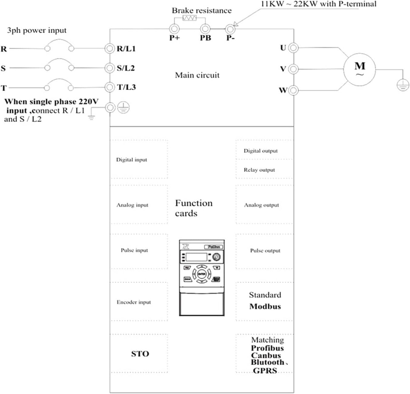
5.2 Wiring
All wiring must be performed by a qualified electrician in accordance with local and national electrical codes. Use appropriate wire gauges for the power input and motor connections.
- Power Input (R/L1, S/L2, T/L3): Connect the main power supply. For 220V single-phase input, connect to R/L1 and S/L2. For 220V three-phase input, connect to R/L1, S/L2, and T/L3.
- Motor Output (U, V, W): Connect these terminals directly to the motor's U, V, W terminals. Do not connect any capacitors or surge suppressors between the VFD and the motor.
- Ground (PE): Ensure a solid ground connection for both the inverter and the motor.
- Brake Resistance (P+, PB, P-): If a brake resistor is required for applications with rapid deceleration or high inertia loads, connect it to the P+ and PB terminals.
- Control Terminals: Refer to the detailed wiring diagram for connections of digital inputs, analog inputs, relay outputs, and communication interfaces.

6. Operating Instructions
6.1 Control Panel Functions
The VFD inverter features a digital display and a keypad for monitoring and control.
- PRG (Program): Enters/exits parameter setting mode.
- RUN: Starts the motor.
- STOP/RESET: Stops the motor or clears fault alarms.
- ENTER: Confirms parameter settings or enters sub-menus.
- Up/Down Arrows: Navigate through parameters or adjust values.
- Left/Right Arrows: Shift cursor during parameter editing.
- M (Mode): Switches display modes (e.g., frequency, current, voltage).
6.2 Basic Operation
- Power On: Apply main power to the inverter. The display will light up.
- Set Frequency: Use the Up/Down arrows to adjust the output frequency (motor speed) if operating in manual mode.
- Start Motor: Press the RUN button. The motor will accelerate to the set frequency.
- Stop Motor: Press the STOP/RESET button. The motor will decelerate and stop.
6.3 Parameter Settings
The VFD inverter has numerous parameters that can be configured to match specific motor and application requirements. These include motor parameters, acceleration/deceleration times, control modes, and protection settings. Refer to the comprehensive parameter list in the full technical manual for detailed descriptions and adjustment procedures.
- Press PRG to enter parameter setting mode.
- Use Up/Down arrows to navigate through parameter groups and individual parameters.
- Press ENTER to view or modify a parameter's value.
- Use Up/Down arrows to change the value, and Left/Right arrows to shift the cursor.
- Press ENTER again to save the new value.
- Press PRG to exit parameter setting mode.
7. Maintenance
Regular maintenance ensures the longevity and reliable operation of your VFD inverter.
- Cleaning: Periodically clean the exterior of the inverter and cooling fins with a soft, dry cloth. Ensure power is disconnected before cleaning. Do not use liquid cleaners.
- Fan Inspection: Check the cooling fan for dust accumulation and ensure it operates freely. Clean or replace if necessary.
- Terminal Check: Annually inspect all wiring terminals for tightness and signs of corrosion. Retighten if loose.
- Environmental Check: Ensure the operating environment remains within specified temperature and humidity ranges.


8. Troubleshooting
This section provides solutions to common issues. For complex problems, contact technical support.
| Problem | Possible Cause | Solution |
|---|---|---|
| Inverter does not power on | No input power; Blown fuse; Incorrect wiring | Check power supply; Inspect fuses; Verify wiring connections. |
| Motor does not run | Incorrect parameters; Motor wiring error; Overload | Check motor parameters (voltage, current, frequency); Verify motor wiring; Reduce load. |
| Overcurrent fault (OC) | Sudden load change; Short circuit in motor/cables; Acceleration time too short | Check motor and cables; Increase acceleration time; Reduce load. |
| Overvoltage fault (OV) | Regenerative braking; Input voltage too high; Deceleration time too short | Install brake resistor; Check input voltage; Increase deceleration time. |
| Overheat fault (OH) | Poor ventilation; Ambient temperature too high; Cooling fan failure | Improve ventilation; Reduce ambient temperature; Check/replace cooling fan. |
9. Warranty and Support
For warranty information, please refer to the terms and conditions provided at the time of purchase or contact your vendor. For technical support, inquiries, or service, please reach out to the manufacturer, EFZRZYJ, or your authorized distributor. Ensure you have your product model and serial number available when contacting support.


