Introduction
This instruction manual provides essential information for the safe and efficient installation, operation, and maintenance of your Y&H GM-D20-SA MPPT Solar Charge Controller. Please read this manual thoroughly before installation and use to ensure optimal performance and longevity of the product.
Safety Information
Important Safety Precautions:
- Always connect the battery first, then the solar panel, and finally the load. Ensure correct polarity (+ and -) for all connections. Reversing polarity can damage the controller and connected devices.
- Install the controller in a well-ventilated area, away from direct sunlight, high temperatures, and moisture.
- Do not disassemble or attempt to repair the controller yourself. Refer to qualified personnel for service.
- Ensure all wiring is correctly sized for the current and voltage to prevent overheating and fire hazards.
- Wear appropriate personal protective equipment (PPE) during installation, including insulated gloves and eye protection.
Product Overview
The Y&H GM-D20-SA is an advanced Maximum Power Point Tracking (MPPT) solar charge controller designed to optimize power harvesting from your solar panels and efficiently charge your battery bank. It features high conversion efficiency, automatic voltage recognition, and comprehensive protection functions.
Key Features:
- Advanced MPPT technology for maximum power point tracking, even with partial shading.
- High charging efficiency (up to 99.9% MPPT, 98% conversion) compared to traditional PWM controllers.
- Ultra-fast I-V curve response for efficient operation.
- Automatic 12V/24V battery voltage recognition.
- LCD display for real-time system status and fault diagnosis.
- Over-temperature protection and intelligent temperature compensation.
- Compatible with Gel, Sealed, Flooded, and Lithium battery types, including 0V lithium battery charging.
- High voltage input capability (up to 50V DC PV input) to reduce wiring costs.
- Comprehensive electronic protection for safe and stable system operation.
- Improved heat dissipation for enhanced durability.
- Current-limiting charging mode and support for instantaneous high-current startup and capacitive loads.
Controller Components:

Image Description: This image displays the Y&H MPPT Solar Charge Controller's backlight LCD screen and its connection terminals. The screen shows various indicators for solar panel, charging, battery, discharging, load, battery percentage, unit, and parameter settings. Below the screen, the four main terminals are labeled: (1) Solar Terminal, (2) Battery Terminal, (3) Load Terminal, and (4) Parallel Communication Port.
- LCD Display: Shows real-time system data, charging status, and error codes.
- Buttons (ESC, UP, DOWN, SET): For navigation and parameter configuration.
- Solar Terminal (PV Input): Connects to solar panels.
- Battery Terminal: Connects to the battery bank.
- Load Terminal: Connects to DC loads.
- Parallel Communication Port: For advanced system configurations or monitoring (if applicable).
Setup and Installation
Proper installation is crucial for the safe and efficient operation of your solar charge controller. Follow these steps carefully:
1. Mounting Location:

Image Description: This image shows the dimensions of the Y&H MPPT Solar Charge Controller (13.5cm/5.31in height and width, 5.5cm/2.17in depth). It also provides an important note: "The controller should be installed in a well-ventilated place, avoid direct sunlight, high temperature and do not install in location where water can enter the controller."
- Choose a well-ventilated indoor location.
- Avoid direct sunlight, high temperatures, and areas where water can enter the controller.
- Ensure sufficient clearance around the controller for heat dissipation.
2. Wiring Sequence:

Image Description: This diagram illustrates the connection sequence for a solar power system using the Y&H MPPT Solar Charge Controller. It shows solar panels connected to the controller, the controller connected to a 12V/24V battery bank, and an inverter connected to the battery bank, which then powers AC loads. A DC load is also shown connected directly to the controller. A critical safety warning is included: "For safety during installation, connect the batteries first, then the solar panel, and finally the load. Please guarantee that the positive and negative poles of each wire are not reversed. When wiring, follow the sequence of connecting the "+" pole first, then the "-" pole."
- Connect the Battery: Connect the battery to the controller's battery terminals. Ensure correct polarity. The controller will automatically detect the battery voltage (12V or 24V).
- Connect the Solar Panel: Connect the solar panel to the controller's PV input terminals. Ensure correct polarity. The maximum PV input voltage is 50V DC.
- Connect the Load (Optional): Connect your DC loads to the controller's load terminals. Ensure correct polarity.
WARNING: Always follow the connection sequence: Battery → Solar Panel → Load. Disconnect in the reverse order: Load → Solar Panel → Battery.
Operating Instructions
Once installed, the controller will begin operating automatically. The LCD display provides real-time information about your system.
LCD Display and Button Functions:
- ESC: Exit current menu or return to the previous screen.
- UP/DOWN: Navigate through menu options or adjust parameter values.
- SET: Enter menu, confirm selection, or save parameter changes.
The display shows various parameters such as PV voltage, battery voltage, charging current, load current, and battery state of charge. Refer to the "Product Overview" section for a visual guide to the LCD indicators.
Battery Type Selection:
The controller supports various battery types. It is essential to select the correct battery type for optimal charging and battery longevity. Use the SET and UP/DOWN buttons to navigate to the battery type setting and select from:
- GEL: Gel batteries.
- SLD: Sealed Lead-Acid batteries.
- FLD: Flooded Lead-Acid batteries.
- LI: Lithium-Ion batteries.
- USER: User-defined parameters for custom battery types.
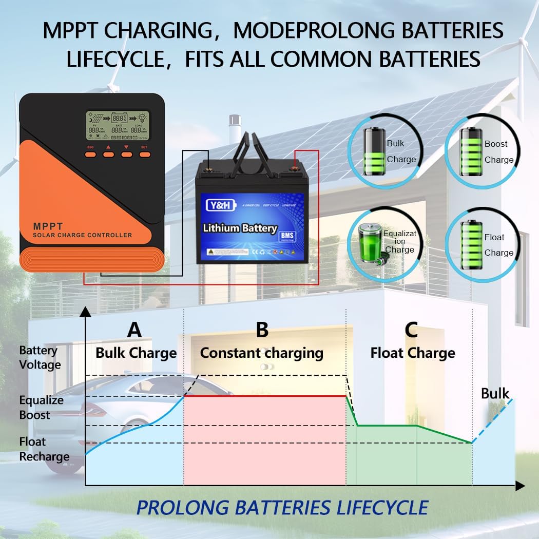
Image Description: This image illustrates the MPPT charging process and its benefits for battery lifecycle. It shows different charging stages (Bulk Charge, Constant Charging, Float Charge) and how the controller adapts to various battery types (Bulk, Boost, Equalization, Float). The graph below depicts battery voltage over time during these charging phases, emphasizing how MPPT prolongs battery life.
The controller employs a multi-stage charging algorithm (Bulk, Boost, Float, Equalization) to ensure efficient and safe charging, extending battery lifespan.
Maintenance
Regular maintenance helps ensure the long-term performance and safety of your solar charge controller and system.
- Check Connections: Periodically inspect all wiring connections for tightness and corrosion. Tighten any loose connections.
- Clean Controller: Keep the controller clean and free of dust. Use a dry cloth to wipe the exterior. Do not use liquids or solvents.
- Ventilation: Ensure that the ventilation openings are not blocked to allow for proper heat dissipation.
- Battery Inspection: Check battery terminals for corrosion and clean if necessary. Monitor battery fluid levels for flooded batteries.
- System Performance: Monitor the LCD display for any error codes or unusual readings.
Troubleshooting
If you encounter issues with your solar charge controller, refer to the following common problems and solutions:
| Problem | Possible Cause | Solution |
|---|---|---|
| No display/Controller not powering on | Battery not connected or low voltage; reversed battery polarity; loose connections. | Check battery connections and voltage. Ensure correct polarity. Tighten all connections. |
| No charging from solar panel | Solar panel not connected; low solar input voltage; reversed PV polarity; shaded panels. | Check PV connections and polarity. Ensure panels are receiving adequate sunlight. Verify PV voltage is within range. |
| Load not working | Load not connected; reversed load polarity; load overcurrent; battery low voltage disconnect. | Check load connections and polarity. Reduce load. Charge battery. |
| Over-temperature error | Poor ventilation; high ambient temperature; excessive load. | Improve ventilation. Reduce ambient temperature. Reduce load. |
| Incorrect battery voltage detection | Battery voltage outside auto-detection range during initial connection. | Ensure battery voltage is within 9-32V. Disconnect and reconnect battery. |
If the problem persists after attempting these solutions, please contact customer support.
Specifications
| Parameter | Value |
|---|---|
| Model | GM-D20-SA |
| Rated Load Current | 20A |
| System Voltage | 12V/24V Auto Recognition |
| Max PV Input Voltage | 50V DC |
| Battery Voltage Range | 9-32V |
| Max Power Point Voltage Range | Battery Voltage +2V to 50V |
| No-load Voltage | ≤0.4W |
| MPPT Efficiency | Up to 99.9% |
| Conversion Efficiency | Up to 98% |
| Battery Types Supported | Gel, Sealed, Flooded, Lithium, User-defined |
| Dimensions | 17 x 16 x 8 cm (approx. 6.7 x 6.3 x 3.15 inches) |
| Weight | 600 grams (approx. 1.32 lbs) |
| EMC Compliance | EN61000, EN55022, EN55024 |
Warranty and Support
For warranty information or technical support, please refer to the retailer where you purchased this product or visit the official Y&H website. Keep your purchase receipt as proof of purchase.
Contact Information: (Please refer to your product packaging or retailer's website for specific contact details.)