1. Introduction
This manual provides essential information for the safe and efficient installation, operation, and maintenance of the YMZYEKB ACS355-01E-04A7-2 Inverter. Please read this manual thoroughly before attempting to install or operate the device. Retain this manual for future reference.
2. Safety Information
WARNING: Electrical shock hazard. Only qualified personnel should perform installation and maintenance procedures. Disconnect all power before servicing.
- Ensure the inverter is installed in a dry, well-ventilated area, free from direct sunlight and excessive dust.
- Verify that the input voltage matches the inverter's specifications (200-240 V).
- Proper grounding is essential to prevent electrical hazards.
- Do not operate the inverter with damaged cables or if the enclosure is open.
- Always wear appropriate personal protective equipment (PPE) when working with electrical equipment.
3. Product Overview
The ACS355-01E-04A7-2 is a robust inverter designed for various industrial applications. It features an open-type enclosure with IP20 protection, suitable for cabinet building. Key features include:
- Input Voltage: 200-240 V
- Frequency: 50/60 Hz
- Output Current (Normal Use): 4.7 A
- Output Power (Normal Use): 0.75 kW
- Degree of Protection: IP20
- Communication Protocols: MODBUS, LON, DeviceNet, PROFIBUS, CAN, EtherNet/IP, PROFINET IO, TCP/IP, RS-232, RS-485.
- Analog Inputs: 2
- Analog Outputs: 1
- Digital In/Outputs: 5/1
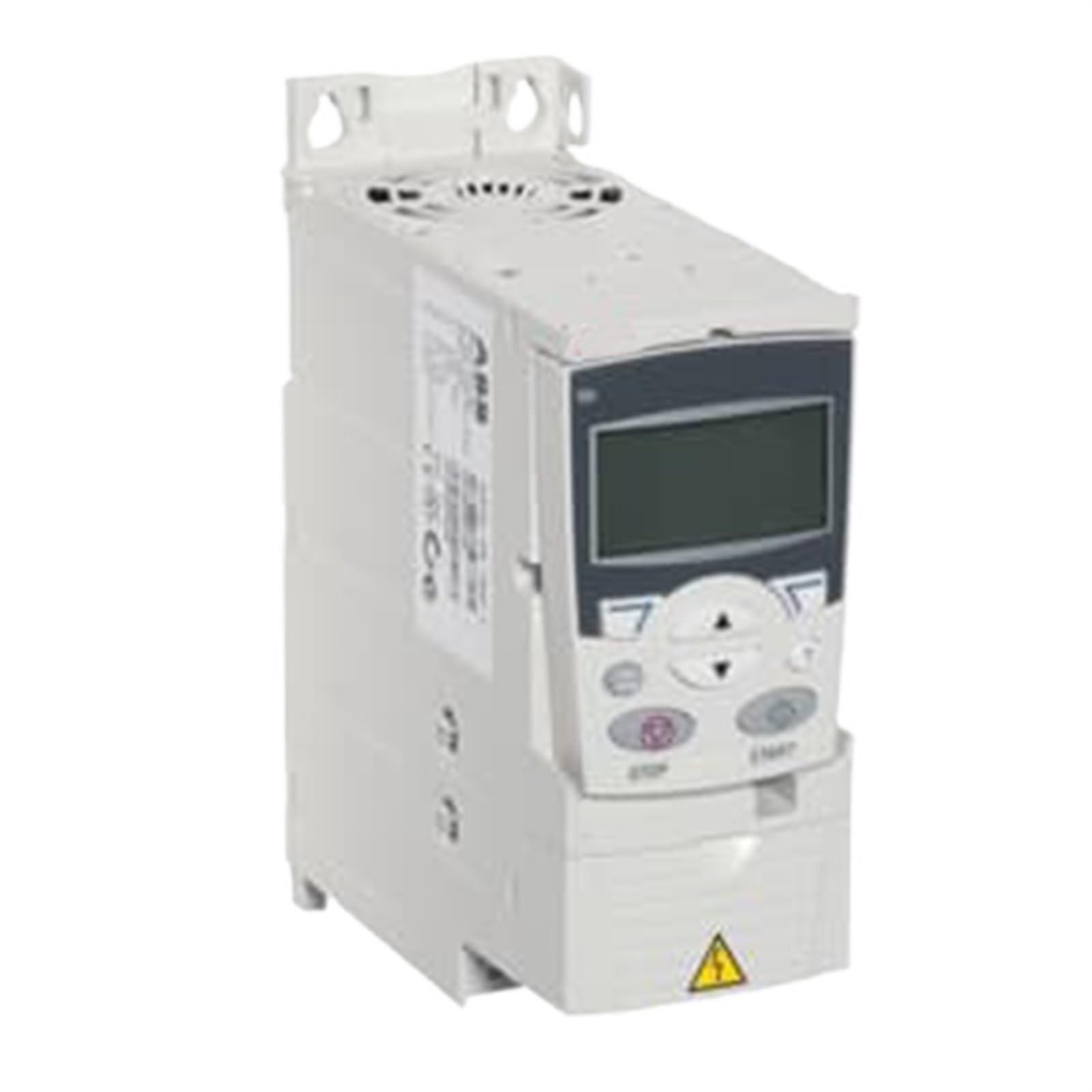
Figure 3.1: Front view of the ACS355-01E-04A7-2 Inverter, showing control panel and connection terminals.
4. Setup and Installation
4.1. Mounting
The inverter is designed for module-based cabinet building. Ensure adequate space for ventilation around the unit. Mount the inverter vertically on a stable surface using appropriate fasteners. Refer to the dimensional specifications for mounting hole locations.
4.2. Wiring
All wiring must comply with local electrical codes and regulations. Use appropriately sized cables for input power, motor connections, and control signals.
- Power Input: Connect the 200-240 V AC single-phase power supply to the designated input terminals (L1, L2).
- Motor Connection: Connect the motor phases to the output terminals (U, V, W).
- Grounding: Connect the protective earth (PE) terminal to a reliable ground point.
- Control Wiring: Connect analog inputs (2), analog outputs (1), and digital I/O (5 inputs, 1 output) as required for your application. Refer to the wiring diagram for specific terminal assignments.
Note: This model includes a PC connection for configuration and monitoring.
5. Operating Instructions
5.1. Initial Power-Up
After completing all wiring and safety checks, apply power to the inverter. The unit will perform a self-diagnostic check. Observe any error codes or indicators.
5.2. Basic Operation
The inverter can be controlled via its digital inputs or through a connected communication protocol (e.g., MODBUS). Consult the detailed programming manual for specific parameter settings related to motor control, speed reference, and acceleration/deceleration ramps.
- Start/Stop: Typically controlled by a digital input or communication command.
- Speed Control: Can be set via analog input (e.g., 0-10V, 4-20mA) or digital communication.
- Monitoring: Output current, frequency, and status can be monitored via analog outputs or communication interfaces.
6. Maintenance
Regular maintenance ensures the longevity and reliable operation of your inverter. Always disconnect power before performing any maintenance.
- Cleaning: Periodically clean the exterior of the inverter and ventilation openings to prevent dust accumulation. Use a soft, dry cloth. Do not use liquid cleaners.
- Inspection: Annually inspect all wiring connections for tightness and signs of wear or damage. Check for any discoloration or unusual odors.
- Environmental Check: Ensure the operating environment remains within specified temperature and humidity ranges.
7. Troubleshooting
This section provides solutions to common issues. For problems not listed here, contact technical support.
| Problem | Possible Cause | Solution |
|---|---|---|
| Inverter does not power on | No input power; Blown fuse; Incorrect wiring | Check power supply; Inspect fuses; Verify wiring connections. |
| Motor not running | Incorrect control signal; Motor fault; Parameter error | Check control wiring; Inspect motor; Verify inverter parameters. |
| Overload fault | Motor overloaded; Incorrect motor parameters; Inverter undersized | Reduce motor load; Adjust motor parameters; Ensure inverter matches motor rating. |
| Overvoltage/Undervoltage fault | Unstable input power supply | Check input voltage stability; Use a voltage regulator if necessary. |
8. Technical Specifications
| Parameter | Value |
|---|---|
| Model | ACS355-01E-04A7-2 |
| Number of Phases | 1 |
| Degree of Protection | IP20 |
| Enclosure Type | Open Type |
| Frequency (f) | 50/60 Hz |
| Input Voltage (Uin) | 200-240 V |
| Mounting Type | Module for cabinet building |
| Output Current, Normal Use (In) | 4.7 A |
| Output Power, Light-Overload Use (PLD) | 0.75 kW |
| Output Power, Normal Use (Pn) | 0.75 kW |
| Analog Inputs | 2 |
| Analog Outputs | 1 |
| Number of Digital In/Outputs | 5/1 |
| Communication Protocols | MODBUS, LON, DeviceNet, PROFIBUS, CAN, EtherNet/IP, PROFINET IO, TCP/IP, RS-232, RS-485 |
| Package Dimensions | 0.39 x 0.39 x 0.39 inches |
| Item Weight | 1.76 ounces (50 Grams) |
9. Warranty and Support
For warranty information, please refer to the documentation provided with your purchase or visit the official YMZYEKB website. Technical support is available for assistance with installation, operation, and troubleshooting. Please have your model number and purchase details ready when contacting support.
Contact Information: Refer to your product packaging or the manufacturer's official website for the most current support contact details.