1. Introduction
This manual provides detailed instructions for the safe and effective operation of the NYGOXSXA MS890A Digital Multimeter. This device is designed for measuring AC/DC voltage, current, resistance, diode, continuity, and more, making it an essential tool for electrical testing and troubleshooting.
Please read this manual thoroughly before using the multimeter and keep it for future reference.
2. Safety Information
Always adhere to the following safety precautions to prevent personal injury or damage to the multimeter or equipment under test.
- Do not exceed the maximum input values specified for each range.
- Use caution when working with voltages above 60V DC or 30V AC RMS, as they pose a shock hazard.
- Before measuring current, ensure the circuit is de-energized and the multimeter is connected in series.
- Before measuring resistance, continuity, or diode, ensure the circuit is de-energized and all capacitors are discharged.
- Inspect test leads for damage before use. Do not use if insulation is compromised.
- Replace the battery when the low battery indicator appears to ensure accurate readings.
- Do not operate the multimeter if it appears damaged or is not functioning properly.
- Adhere to local and national safety codes.
3. Product Features
The MS890A Digital Multimeter offers a range of features for various electrical measurements:
- Frequency measurement: 400Hz
- Overload Protection
- Transistor Test
- Diode Test
- Continuity Test
- LED Test
- Maximum Display: 2000 counts
- Safety Rating: IV 600V / III 1000V
- Relative Measurement mode
- Auto Power Off function
- Data Hold function
- Built-in Flashlight
Note: Other models (MS890B, MS890C+, MS890D+) in this series may offer additional features such as higher frequency ranges, Non-Contact Voltage (NCV) detection, Live Wire recognition, higher display counts, backlight, and dual backlight. This manual specifically covers the MS890A model.
4. Components and Controls

Figure 4.1: Front view of the MS890A Digital Multimeter. This image displays the large LCD screen, the central rotary function switch, and the input terminals for test leads. Key buttons like 'Power' and 'Hold' are also visible.
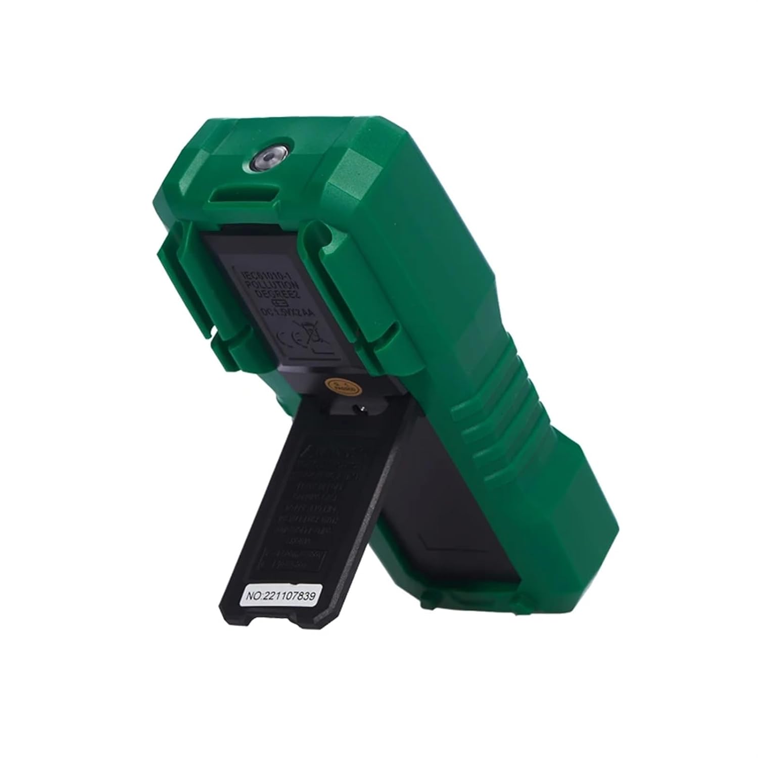
Figure 4.2: Side view of the MS890A Digital Multimeter with its integrated kickstand extended. This stand allows the meter to be propped up for easier viewing during use.

Figure 4.3: Back view of the MS890A Digital Multimeter. This view shows the battery compartment cover, product identification labels, and safety compliance markings.
4.1. Display
The LCD displays measurement readings, units, function indicators, and low battery warning.
4.2. Rotary Function Switch
Used to select the desired measurement function (e.g., V~ for AC Voltage, V- for DC Voltage, Ω for Resistance, A for Current, etc.).
4.3. Input Jacks
- COM Jack: Common terminal for all measurements. Connect the black test lead here.
- VΩmA Jack: Input for voltage, resistance, diode, continuity, and small current measurements. Connect the red test lead here.
- 10A Jack: Input for high current measurements (up to 10A). Connect the red test lead here for current measurements exceeding the mA range.
4.4. Buttons
- POWER: Turns the multimeter ON/OFF.
- HOLD: Freezes the current reading on the display. Press again to release.
- REL (Relative): Measures the difference between a stored value and the current reading.
5. Setup
5.1. Battery Installation
The MS890A multimeter requires batteries for operation (battery not included). Refer to Figure 4.3 for the battery compartment location.
- Ensure the multimeter is turned off.
- Locate the battery compartment cover on the back of the unit.
- Unscrew the retaining screw(s) and remove the cover.
- Insert the correct type and number of batteries, observing polarity (+ and -).
- Replace the battery compartment cover and secure it with the screw(s).
5.2. Connecting Test Leads
Always connect the black test lead to the COM jack. Connect the red test lead to the appropriate input jack based on the measurement function:
- For Voltage, Resistance, Diode, Continuity, and small Current (mA) measurements: Connect the red lead to the VΩmA jack.
- For high Current (10A) measurements: Connect the black test lead to the COM jack and the red test lead to the 10A jack.
6. Operating Instructions
Before taking any measurement, ensure the test leads are correctly connected and the rotary switch is set to the desired function.
6.1. Measuring DC Voltage (V-)
- Set the rotary switch to the V- range.
- Connect the black test lead to the COM jack and the red test lead to the VΩmA jack.
- Connect the test leads in parallel across the DC voltage source to be measured.
- Read the voltage value on the display.
6.2. Measuring AC Voltage (V~)
- Set the rotary switch to the V~ range.
- Connect the black test lead to the COM jack and the red test lead to the VΩmA jack.
- Connect the test leads in parallel across the AC voltage source to be measured.
- Read the voltage value on the display.
6.3. Measuring Resistance (Ω)
- Ensure the circuit is de-energized.
- Set the rotary switch to the Ω range.
- Connect the black test lead to the COM jack and the red test lead to the VΩmA jack.
- Connect the test leads across the component whose resistance is to be measured.
- Read the resistance value on the display.
6.4. Continuity Test
- Ensure the circuit is de-energized.
- Set the rotary switch to the continuity/diode range (often indicated by a speaker icon).
- Connect the black test lead to the COM jack and the red test lead to the VΩmA jack.
- Connect the test leads across the circuit or component.
- If continuity exists (resistance below a certain threshold), the multimeter will emit an audible beep. The display will show the resistance value.
6.5. Diode Test
- Ensure the circuit is de-energized.
- Set the rotary switch to the continuity/diode range (often indicated by a diode symbol).
- Connect the black test lead to the COM jack and the red test lead to the VΩmA jack.
- Connect the red test lead to the anode and the black test lead to the cathode of the diode.
- Read the forward voltage drop on the display. Reverse the leads; an open circuit (OL) reading indicates a good diode.
6.6. Measuring DC Current (A-, mA-, µA-)
- Ensure the circuit is de-energized.
- Set the rotary switch to the appropriate A-, mA-, or µA- range.
- For mA or µA: Connect the black test lead to the COM jack and the red test lead to the VΩmA jack.
- For 10A: Connect the black test lead to the COM jack and the red test lead to the 10A jack.
- Break the circuit and connect the multimeter in series with the load.
- Apply power to the circuit and read the current value on the display.
6.7. Transistor Test (hFE)
- Set the rotary switch to the hFE range.
- Identify the type of transistor (NPN or PNP) and its Emitter, Base, Collector leads.
- Insert the transistor leads into the corresponding holes in the hFE socket on the multimeter.
- Read the hFE value (DC current gain) on the display.
6.8. LED Test
- Set the rotary switch to the LED test range.
- Connect the black test lead to the COM jack and the red test lead to the VΩmA jack.
- Connect the red test lead to the anode and the black test lead to the cathode of the LED.
- The LED should light up, and the display will show its forward voltage drop.
6.9. Auto Power Off
The multimeter will automatically power off after a period of inactivity to conserve battery life. Press any button or turn the rotary switch to reactivate the unit.
6.10. Data Hold
Press the 'HOLD' button to freeze the current reading on the display. This is useful for taking readings in hard-to-reach areas. Press 'HOLD' again to release the reading.
6.11. Flashlight
The MS890A includes a built-in flashlight for illuminating the test area. Refer to the device for the specific button or switch to activate the flashlight.
7. Maintenance
7.1. Cleaning
Wipe the case with a damp cloth and mild detergent. Do not use abrasives or solvents. Ensure the multimeter is completely dry before use.
7.2. Battery Replacement
When the low battery indicator appears on the display, replace the batteries immediately to ensure accurate measurements. Follow the steps in Section 5.1. Battery Installation.
7.3. Fuse Replacement
If the current measurement function stops working, the fuse may need replacement. Refer to the specific fuse ratings printed near the input jacks or inside the battery compartment. Fuse replacement should only be performed by qualified personnel.
8. Troubleshooting
| Problem | Possible Cause | Solution |
|---|---|---|
| No display or dim display | Dead or low batteries | Replace batteries (refer to Section 5.1). |
| "OL" (Overload) displayed | Input value exceeds selected range or meter's maximum capacity. | Select a higher range or ensure the input is within the meter's specifications. |
| Incorrect readings | Incorrect function selected, poor test lead connection, or low battery. | Verify function setting, check test lead connections, replace batteries. |
| Current measurement not working | Blown fuse. | Replace the fuse (refer to Section 7.3). |
9. Specifications
| Parameter | Value (MS890A) |
|---|---|
| Max Display | 2000 counts |
| Frequency | 400Hz |
| Safety Rating | IV 600V / III 1000V |
| Item Weight | 50 Grams (approx. 1.76 ounces) |
| Package Dimensions | 0.39 x 0.39 x 0.39 inches |
| Model Number | NYGOXSXA (Manufacturer's internal model number) |
| ASIN | B0F91NSKPY |
10. Warranty and Support
For warranty information or technical support regarding your NYGOXSXA MS890A Digital Multimeter, please contact the seller or manufacturer directly. Refer to your purchase documentation for specific warranty terms and contact details.
General support inquiries can often be directed to the point of purchase or the manufacturer's official website.