1. Introduction
1.1. Overview
This manual provides detailed instructions for the installation, operation, and maintenance of the YUANWIN YW-TF501-1200lb All-in-One Door Access Control System Kit. This system is designed to provide secure and convenient access management for various environments, including homes, offices, garages, and warehouses. It integrates multiple access methods such as fingerprint, RFID card, PIN code, and remote control.
1.2. Package Contents
Verify that all components listed below are present in your package:
- IP68 Waterproof Metal Keypad with Fingerprint, RFID, and PIN access
- 1200lb Electromagnetic Lock
- Power Supply Control Unit
- Waterproof Infrared Exit Button
- 2 Remote Controls and Receiver
- Doorbell Unit
- Power Cord
- RFID Cards/Key Fobs (typically 5 included)
- Mounting Hardware and Wiring Accessories

Image 1.1: All components included in the YUANWIN YW-TF501-1200lb Access Control System Kit. This includes the keypad, magnetic lock, power supply, exit button, remote controls, doorbell, and RFID key fobs.
2. Safety Information
Please read and understand all safety instructions before installation and operation. Failure to follow these instructions may result in electric shock, fire, or serious injury.
- Electrical Safety: Ensure all power is disconnected before performing any wiring or installation. Work with qualified electricians if you are unsure about electrical connections.
- Voltage: The power supply operates with AC110V-240V input and DC12V output. Verify correct voltage connections.
- Water Resistance: The keypad is IP68 waterproof. However, ensure all connections are properly sealed and protected from direct water exposure during installation.
- Mounting: Mount all components securely to prevent accidental detachment.
- Children: Keep small components and tools out of reach of children.
3. Product Components
3.1. IP68 Waterproof Metal Keypad
This durable stainless steel touch keypad features an LCD screen for intuitive menu navigation. It supports multiple access methods: fingerprint, RFID card, and PIN code. No external software is required for setup.

Image 3.1: Detailed view of the access control keypad, showing the numeric touch interface, LCD display, and fingerprint reader.
3.2. 1200lb Electromagnetic Lock
A heavy-duty magnetic lock designed for secure door closure, offering a 1200-pound holding force. Its waterproof design makes it suitable for both indoor and outdoor applications. Includes the main magnet unit and the armature plate.
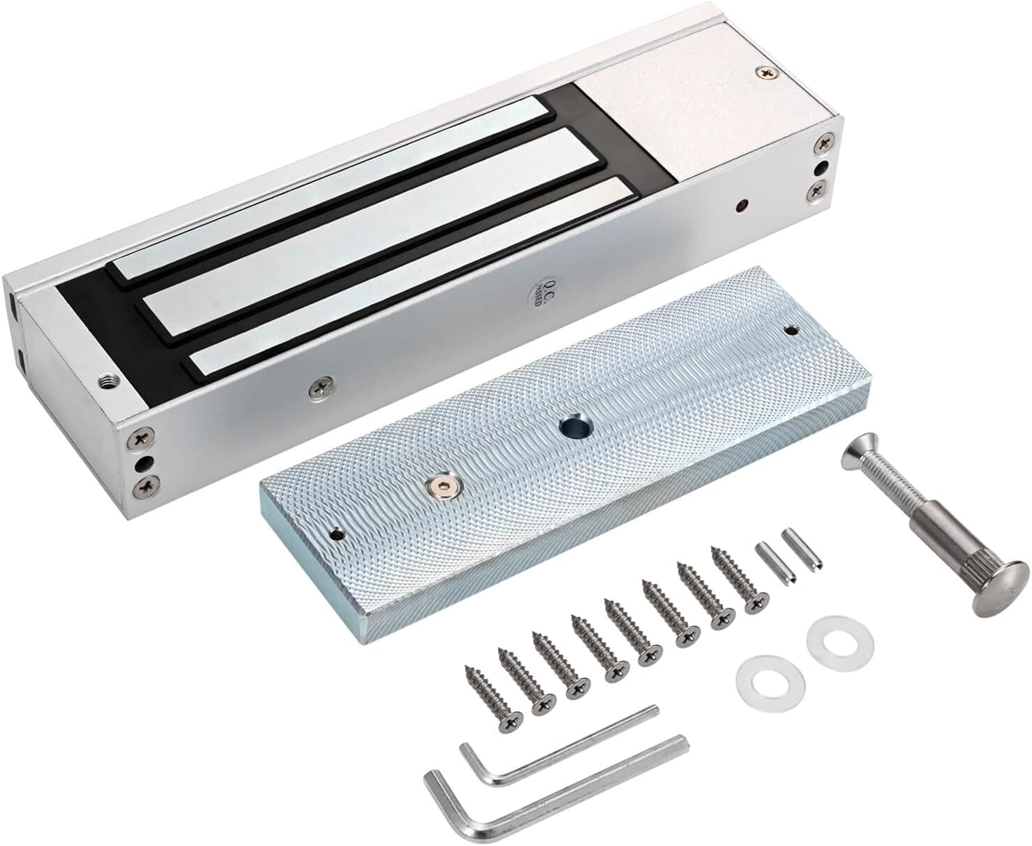
Image 3.2: The electromagnetic lock and its corresponding armature plate, along with mounting hardware.
3.3. Power Supply Control Unit
This unit converts AC power to DC12V (4A) to power the entire access control system. It features various terminals for connecting the keypad, lock, exit button, and doorbell, and includes safety warnings regarding hazardous voltage.

Image 3.3: The power supply unit with input/output specifications and wiring terminals.
3.4. Waterproof Infrared Exit Button
A touch-free stainless steel exit button that uses infrared technology for activation. It supports both surface and flush mounting, providing flexible installation options for exiting the secured area.

Image 3.4: The infrared exit button mounted on a wall next to a door, indicating 'WAVE TO OPEN'.
3.5. Remote Controls and Receiver
The kit includes two remote controls for wireless access. These remotes communicate with a receiver module, which then signals the access control system to unlock the door. This provides an additional layer of convenience for authorized personnel.
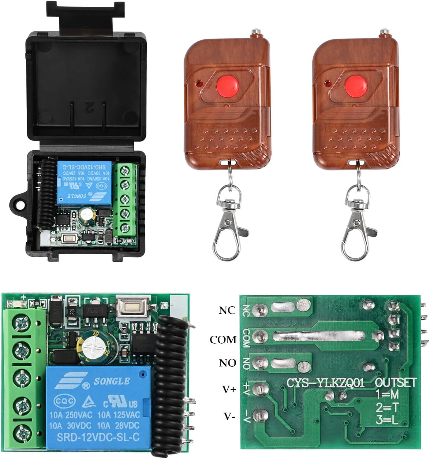
Image 3.5: Two remote controls and the associated receiver module for wireless door access.
3.6. Doorbell Unit
A simple doorbell unit that produces a 'Ding Dong' sound when activated. It connects to the keypad and alerts occupants inside when a visitor presses the doorbell button on the keypad.

Image 3.6: The doorbell unit, showing its compact design and labeled wiring for connection.
4. Setup and Installation
Careful planning and execution are crucial for optimal performance and security. Ensure all power is off before beginning any wiring.
4.1. System Overview
Understand the general layout of the system components and their placement relative to the door. The keypad is typically installed on the exterior, while the exit button and doorbell are on the interior. The magnetic lock is mounted on the door frame and door.

Image 4.1: A visual representation of the access control system components installed on a double door, indicating exterior and interior placements.
4.2. Wiring Diagram
Follow the detailed wiring diagram carefully to connect all components to the power supply and keypad. Incorrect wiring can damage the system or pose a safety risk.

Image 4.2: Comprehensive wiring diagram illustrating connections between the access control keypad, power supply, magnetic lock, exit button, remote receiver, and doorbell.
4.3. Installation Steps
- Mount the Keypad: Choose a suitable location on the exterior wall or door frame. Drill holes, secure the backplate, and connect the keypad wiring according to the diagram.
- Install the Magnetic Lock: Mount the electromagnetic lock to the door frame and the armature plate to the door. Ensure proper alignment for maximum holding force. Refer to the lock's specific mounting instructions for different door types (e.g., L-bracket, Z-bracket if needed).
- Mount the Exit Button: Install the infrared exit button on the interior side of the door, at a convenient height. Connect its wiring to the power supply/keypad as shown in the diagram.
- Install the Power Supply: Mount the power supply control unit in a secure, dry location, typically indoors. Connect the AC input and all DC output wires to the respective components.
- Connect Remote Receiver and Doorbell: Integrate the remote receiver and doorbell unit into the system by following the wiring diagram.
- Test Connections: Before applying full power, double-check all wiring connections for correctness and security.
- Apply Power: Once all connections are verified, connect the power cord to an AC outlet.
5. Operating Instructions
5.1. Initial Setup and Programming
Upon first power-up, the keypad will typically be in a default state. Refer to the keypad's on-screen menu for initial programming steps. This usually involves:
- Setting an Administrator PIN.
- Adding User PINs.
- Enrolling RFID Cards/Key Fobs.
- Registering Fingerprints.
Navigate the menu using the numeric keypad and the designated 'Setup' or 'Menu' button on the LCD screen.
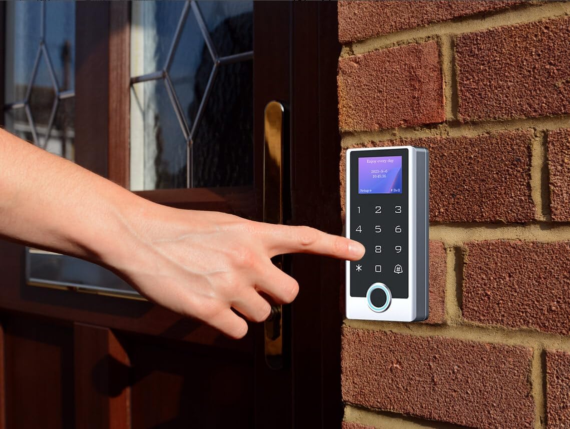
Image 5.1: A user entering a code on the keypad, demonstrating typical operation.
5.2. Access Methods
- PIN Code: Enter your registered PIN code on the keypad, followed by the '#' or 'Enter' key.
- RFID Card: Present your registered RFID card or key fob to the RFID reader area on the keypad.
- Fingerprint: Place your registered finger on the fingerprint sensor on the keypad.
- Remote Control: Press the designated button on the remote control to wirelessly unlock the door.
- Exit Button: Wave your hand in front of the infrared exit button from the inside to unlock the door.
5.3. Doorbell Function
When a visitor presses the doorbell icon or button on the keypad, the interior doorbell unit will sound, alerting occupants.
6. Maintenance
Regular maintenance ensures the longevity and reliable operation of your access control system.
- Cleaning: Clean the keypad and exit button surfaces with a soft, damp cloth. Avoid abrasive cleaners or solvents.
- Fingerprint Sensor: Keep the fingerprint sensor clean and free of dirt or residue for accurate readings.
- Magnetic Lock: Periodically check the magnetic lock and armature plate for any debris or corrosion that might affect the holding force. Ensure the surfaces are clean and flat.
- Wiring: Inspect visible wiring periodically for any signs of wear, damage, or loose connections.
- Power Supply: Ensure the power supply unit is well-ventilated and free from obstructions.
7. Troubleshooting
If you encounter issues with your YUANWIN Access Control System, refer to the following common problems and solutions:
| Problem | Possible Cause | Solution |
|---|---|---|
| Magnetic lock does not engage/disengage. | Loose wiring, insufficient power, faulty lock, misalignment. | Check all wiring connections to the power supply and lock. Verify power supply output. Ensure the lock and armature plate are perfectly aligned. Test the lock independently if possible. |
| Keypad is unresponsive or screen is blank. | No power, loose connection, keypad malfunction. | Check power supply status and keypad wiring. Ensure the power supply is receiving AC input. If issues persist, contact support. |
| RFID card/Fingerprint not recognized. | Card/fingerprint not enrolled, dirty sensor, incorrect placement. | Ensure the card/fingerprint is properly enrolled in the system. Clean the fingerprint sensor. Ensure correct placement of the card/finger on the reader. |
| Remote control does not work. | Remote battery low, receiver not powered, remote not paired. | Replace remote battery. Check power and wiring to the remote receiver. Re-pair the remote control with the receiver if necessary (refer to receiver instructions). |
| Doorbell does not ring. | Loose wiring, faulty doorbell unit. | Check wiring connections to the doorbell unit from the keypad. Ensure the doorbell unit is receiving power. |
8. Specifications
| Feature | Specification |
|---|---|
| Brand | YUANWIN |
| Model Number | YW-TF501-1200lb |
| Keypad Protection Rating | IP68 Waterproof |
| Keypad Material | Stainless Steel |
| Access Methods | Fingerprint, RFID Card, PIN Code, Remote Control |
| Magnetic Lock Holding Force | 1200 lbs |
| Power Supply Input | AC 110V-240V |
| Power Supply Output | DC 12V (4A) |
| Exit Button Type | Infrared Touch-Free |
| Item Dimensions (L x W x H) | 11 x 9 x 4 inches (Product Package) |
| Item Weight | 11 Pounds |
| UPC | 769894489444 |
9. Warranty and Support
For warranty information or technical support, please refer to the product packaging or contact YUANWIN customer service directly. Keep your purchase receipt for warranty claims.