1. Introduction
This manual provides detailed instructions for the proper setup, operation, and maintenance of the FUCCEOGJ T4201-6A Heat Transfer Temperature Control Box. This device is designed as a digital thermostat controller for applications requiring precise temperature and time management, such as in stamping machines and flat ironing equipment. It features a clear digital display for both process value (PV) and set value (SV), along with intuitive controls for temperature and time settings.
2. Product Overview

Figure 2.1: Front and Rear Views. This image displays the front panel of the T4201-6A controller, showing the digital displays for PV (Process Value) and SV (Set Value), along with control buttons for temperature and time adjustments. Adjacent to it is the rear view, illustrating the terminal block for electrical connections, including power input, sensor input, and output relays.

Figure 2.2: Top and Bottom Views. This image provides a perspective of the top and bottom surfaces of the T4201-6A temperature controller. These views highlight the compact design and potential mounting features, such as clips or grooves, which are essential for integrating the unit into control panels or enclosures.
The T4201-6A features a robust design suitable for industrial environments. Its front panel includes two digital displays: the upper display (PV) shows the current measured temperature, and the lower display (SV) shows the set target temperature or time. Control buttons allow for easy adjustment of these parameters. The rear of the unit is equipped with a terminal block for secure and reliable electrical connections.
3. Setup and Installation
Proper installation is crucial for the safe and effective operation of the T4201-6A controller. Ensure all power is disconnected before proceeding with any wiring.
3.1. Mounting
The controller is designed for panel mounting. Ensure adequate space for ventilation and access to wiring terminals. Refer to the dimensions provided in Section 6 for precise cutout requirements.
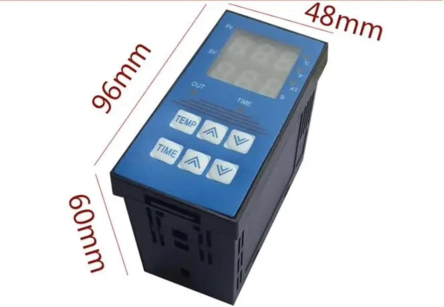
Figure 3.1: Product Dimensions. This image illustrates the physical dimensions of the T4201-6A controller, indicating a width of 48mm, a height of 96mm, and a depth of 60mm. These measurements are critical for planning the installation space and panel cutout.
3.2. Wiring Connections
Connect the power supply, temperature sensor, and output load to the appropriate terminals on the rear of the unit. Consult the wiring diagram typically found on the device casing or in supplementary documentation for specific terminal assignments. Ensure all connections are secure and comply with local electrical codes.
- Power Input: Connect the main power supply (e.g., AC 100-240V) to the designated power terminals.
- Sensor Input: Connect the temperature sensor (e.g., thermocouple, RTD) to the sensor input terminals. Ensure correct polarity if applicable.
- Output Control: Connect the heating element or other controlled device to the output relay terminals.
Caution: Incorrect wiring can damage the unit or pose a safety hazard. If unsure, consult a qualified electrician.
4. Operating Instructions
Once installed and powered on, the T4201-6A is ready for operation. The unit will display the current temperature (PV) and the set temperature (SV).
4.1. Setting Temperature
- Press the TEMP button once to enter temperature setting mode. The SV display will flash.
- Use the UP (▲) and DOWN (▼) arrow buttons next to "TEMP" to adjust the desired temperature.
- Press the TEMP button again to confirm the setting and exit setting mode. The new SV will be saved.
4.2. Setting Time (if applicable)
If your application requires timed operation, the T4201-6A also allows for time setting.
- Press the TIME button once to enter time setting mode. The SV display will flash.
- Use the UP (▲) and DOWN (▼) arrow buttons next to "TIME" to adjust the desired time duration.
- Press the TIME button again to confirm the setting and exit setting mode.
4.3. Display Indicators
- PV (Process Value): Upper display, shows the current measured temperature.
- SV (Set Value): Lower display, shows the target temperature or time setting.
- OUT Indicator: Illuminates when the output relay is active (e.g., heating element is on).
- AT Indicator: May indicate auto-tuning process or alarm status, depending on specific model features.
5. Maintenance
Regular maintenance ensures the longevity and reliable performance of your T4201-6A controller.
- Cleaning: Periodically clean the front panel with a soft, dry cloth. Do not use abrasive cleaners or solvents. Ensure no liquids enter the unit.
- Connections: Periodically check all electrical connections for tightness and signs of corrosion. Loose connections can lead to erratic behavior or damage.
- Environment: Ensure the operating environment remains within the specified temperature and humidity ranges to prevent damage to internal components.
Warning: Disconnect power to the unit before performing any cleaning or maintenance.
6. Troubleshooting
This section provides solutions to common issues you might encounter with the T4201-6A controller. For problems not listed here, please contact customer support.
| Problem | Possible Cause | Solution |
|---|---|---|
| No display/No power | No power supply; Loose wiring; Blown fuse (if applicable) | Check power connections; Verify power source; Inspect wiring for damage; Check fuse. |
| Incorrect temperature reading (PV) | Sensor faulty; Incorrect sensor type selected; Loose sensor connection | Check sensor for damage; Ensure correct sensor type is used; Secure sensor wiring. |
| Output not activating | Set value not reached; Output wiring issue; Internal fault | Verify SV is set correctly; Check output wiring; Consult manufacturer if problem persists. |
| Buttons unresponsive | Temporary software glitch; Physical damage | Power cycle the unit; If problem persists, contact support. |
7. Specifications
| Feature | Detail |
|---|---|
| Model Number | T4201-6A |
| Theory | Temperature Controller |
| Display Type | DIGITAL |
| Power Type | Charger (Implies external power supply) |
| Display Size | 2.0 - 3.9 Inches |
| Max Measuring Temperature | 120°C & Above |
| Style | Standing Station |
| Usage | Industrial |
| Package Dimensions | 1.18 x 0.79 x 0.39 inches |
| Item Weight | 6.2 ounces |
| Manufacturer | FUCCEOGJ |
| ASIN | B0F8WC6Y5Z |
| Assembly Required | No |
| Number of Pieces | 1 |
8. Warranty and Support
8.1. Warranty Information
Specific warranty terms for the T4201-6A Heat Transfer Temperature Control Box are provided by the manufacturer, FUCCEOGJ, or the authorized seller at the time of purchase. Please retain your proof of purchase for warranty claims. For detailed warranty coverage, duration, and conditions, refer to the documentation included with your product or contact the seller directly.
8.2. Customer Support
For technical assistance, operational queries, or troubleshooting beyond the scope of this manual, please contact the seller or manufacturer. When contacting support, please have your product model number (T4201-6A) and purchase details readily available.


