1. Introduction
This manual provides detailed instructions for the installation, operation, and maintenance of your FOIFKIN K6 ATX Mid-Tower PC Case. Please read this manual thoroughly before beginning assembly to ensure proper setup and optimal performance of your system.

Image 1.1: The FOIFKIN K6 PC Case, showcasing its grille design and internal components.
2. Product Overview
The FOIFKIN K6 is an ATX mid-tower PC case designed for gaming systems, featuring a distinctive grille front panel and pre-installed ARGB PWM fans for efficient cooling and aesthetic appeal.
2.1 Key Features
- Grille Design: The front panel integrates a metal grille for enhanced aesthetics and airflow.
- High-Performance Cooling: Equipped with 6 pre-installed ARGB PWM fans (3 x 120mm, 3 x 140mm) for optimized airflow.
- Tool-less Access: Snap-on tempered glass side panel allows for quick removal and easy access to internal components.
- Spacious Interior: Supports ATX, M-ATX, and ITX motherboards, with ample room for large GPUs and CPU coolers.
- Versatile I/O Ports: Front panel includes 1x Type-C 3.0, 1x USB 3.0, 1x USB 2.0, and audio jacks.

Image 2.1: Quick removal of the snap-on tempered glass side panel for convenient access.

Image 2.2: The front panel with six pre-installed ARGB PWM fans for intake cooling.

Image 2.3: The open front grille design, enhancing both aesthetics and airflow.
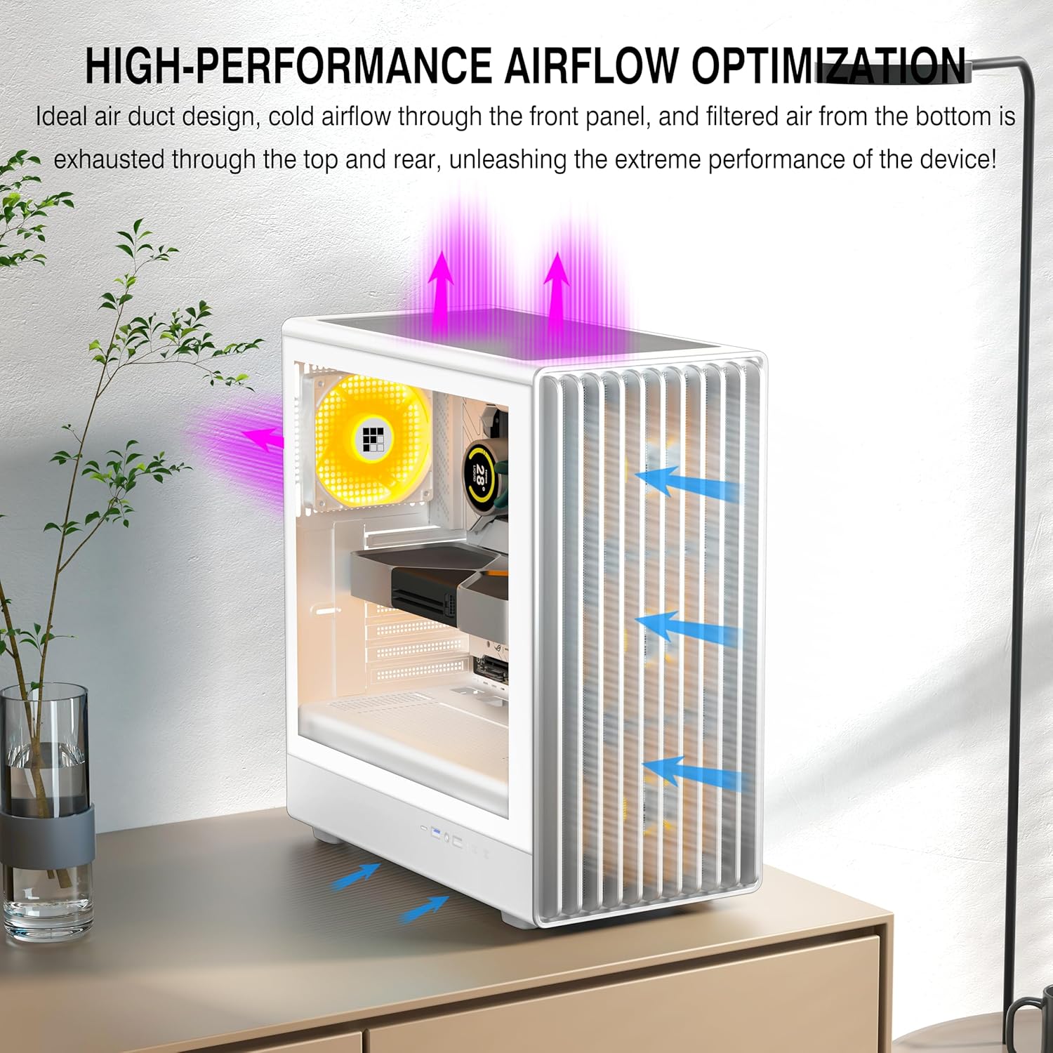
Image 2.4: Airflow optimization within the case, with cold air intake and hot air exhaust.

Image 2.5: The multi-function front I/O panel for convenient connectivity.
3. Specifications
| Feature | Specification |
|---|---|
| Model Name | K6 |
| Case Type | Mid Tower |
| Dimensions (L x W x H) | 370 x 220 x 450 mm (14.6 x 8.7 x 17.7 inches) |
| Weight | 6.26 kg |
| Motherboard Support | ATX, M-ATX, ITX |
| Pre-installed Fans | 6 ARGB PWM Fans (3x 120mm, 3x 140mm) |
| Max CPU Cooler Height | 174 mm |
| Max GPU Length | 319 mm |
| PSU Type Support | ATX up to 170 mm |
| Drive Bays | 2x HDD & 2x SSD or 1x HDD & 3x SSD |
| Expansion Slots | 7 |
| Front I/O Ports | 1x Type-C 3.0, 1x USB 3.0, 1x USB 2.0, Microphone/Audio, Power Button, Reboot Button |
| Cooling Method | Air, Water |

Image 3.1: Internal component compatibility and cooling system layout.

Image 3.2: External dimensions of the FOIFKIN K6 PC Case.
4. Setup and Installation
Follow these steps for assembling your PC components within the FOIFKIN K6 case.
4.1 Preparing the Case
- Place the case on a stable, flat surface.
- Gently pull the tempered glass side panel to detach it from the snap-on mechanism. Set it aside in a safe location.
- Remove the rear side panel (usually secured with thumbscrews) to access the cable management area.
4.2 Motherboard Installation
- Install the I/O shield (if not pre-installed) into the rear opening of the case.
- Align your ATX, M-ATX, or ITX motherboard with the standoffs inside the case. Ensure all standoffs match the motherboard's mounting holes.
- Secure the motherboard with the provided screws.
4.3 Power Supply Unit (PSU) Installation
- Locate the PSU mounting area at the bottom rear of the case.
- Slide your ATX PSU (up to 170mm in length) into position.
- Secure the PSU to the case using screws from the rear.
4.4 Storage Drive Installation
- The case supports 2x HDD and 2x SSD, or 1x HDD and 3x SSD configurations.
- Locate the designated drive bays/mounts behind the motherboard tray or in the PSU shroud area.
- Secure your 2.5-inch SSDs or 3.5-inch HDDs using the appropriate screws or tool-less mechanisms.
4.5 Graphics Card (GPU) Installation
- Remove the necessary expansion slot covers from the rear of the case.
- Insert your GPU (up to 319mm in length) into the appropriate PCIe slot on your motherboard.
- Secure the GPU with screws.

Image 4.1: GPU installation, demonstrating compatibility with modern graphics cards.
4.6 Cable Management
Utilize the space behind the motherboard tray and the cable routing cutouts to manage cables. This improves airflow and aesthetics.
4.7 Connecting Front I/O and Fan Cables
- Connect the front panel cables (USB 3.0, USB 2.0, Type-C, Audio, Power, Reset, LED) to their respective headers on your motherboard. Refer to your motherboard manual for exact pinouts.
- The pre-installed ARGB PWM fans are typically daisy-chained. Connect the fan power cable(s) to your motherboard's fan headers and the ARGB cable(s) to your motherboard's ARGB headers.
- Important Note for Fan Connections: The six pre-installed fans are often linked to a single adapter for motherboard connection. Ensure your motherboard's fan headers can safely supply enough power for all connected fans. Most headers are rated for 1 Amp. If the total current draw of all fans exceeds this, consider using a fan hub with external power or connecting fewer fans to a single header to prevent potential damage to your motherboard.
5. Operation
Once all components are installed and connected, you can power on your system.
5.1 Power On/Off
Press the Power Button on the front I/O panel to turn your system on or off. A short press typically initiates power on, while a longer press (usually 4-5 seconds) will force a shutdown.
5.2 Reset Function
The Reset Button on the front I/O panel can be used to restart your system if it becomes unresponsive.
5.3 Front Panel Connectivity
Utilize the front panel USB 3.0, USB 2.0, and Type-C 3.0 ports for connecting peripherals and external storage devices. The Microphone/Audio jacks allow for easy connection of headsets or microphones.
5.4 ARGB Fan Control
The pre-installed ARGB fans can be controlled via your motherboard's ARGB software (if connected to an ARGB header) or a dedicated ARGB controller (if included or purchased separately). Refer to your motherboard's manual or the controller's instructions for specific ARGB lighting effects and fan speed adjustments.
6. Maintenance
Regular maintenance helps ensure the longevity and optimal performance of your PC case and components.
6.1 Dust Cleaning
- Periodically clean dust filters (if present) and fan blades using compressed air or a soft brush.
- Dust accumulation can impede airflow and reduce cooling efficiency.
- Ensure the system is powered off and unplugged before cleaning.
6.2 Exterior Cleaning
Wipe the exterior surfaces of the case with a soft, damp cloth. Avoid abrasive cleaners or solvents that could damage the finish.
7. Troubleshooting
This section addresses common issues you might encounter.
7.1 System Not Powering On
- Verify that the power supply is properly connected to the wall outlet and switched on.
- Check all power cables from the PSU to the motherboard and components (CPU, GPU, drives).
- Ensure the front panel power button cable is correctly connected to the motherboard's power header.
7.2 Fans Not Spinning or ARGB Not Lighting Up
- Confirm that the fan power cables are securely connected to the motherboard fan headers or a fan controller.
- Ensure ARGB cables are connected to a compatible ARGB header on the motherboard or an ARGB controller.
- Check your motherboard's BIOS/UEFI settings or ARGB software for fan speed and lighting control.
- As noted in Section 4.7, verify that the total current draw of all fans connected to a single motherboard header does not exceed the header's rated capacity (typically 1 Amp). Overloading can prevent fans from operating or damage the motherboard.
7.3 USB Ports Not Functioning
- Ensure the front panel USB cables (USB 3.0, USB 2.0, Type-C) are correctly connected to their respective headers on the motherboard.
- Check your motherboard manual for correct header locations and pinouts.
8. Warranty and Support
FOIFKIN strives to provide quality products and customer satisfaction.
The product quality is guaranteed. If you encounter any issues with your FOIFKIN K6 PC Case, please contact FOIFKIN customer support. You can typically find contact information by visiting the official FOIFKIN store page or through the retailer where the product was purchased. Please provide your product model (K6) and a detailed description of the issue when seeking support.