1. Introduction
The Jauarta MY8236B is a compact and reliable digital multimeter designed for accurate electrical measurements. It features a clear 4000-count display and a new generation layout for enhanced usability. This instrument is suitable for various applications including power electronic circuit measurement, new energy equipment testing, power system strength testing, automotive circuit maintenance, and educational purposes.
Important Safety Note: Always keep the inside of the meter clean and dry to prevent electric shock or damage to the meter. Read all safety warnings and operating instructions before using this instrument.
2. Product Features
- Clear Display: Features a new display and function layout for improved readability.
- 4000 Counts Reading: Provides industrial-grade readings up to 4000 counts for precise measurements.
- Wide Application: Versatile for power electronics, new energy, automotive, and educational testing.
- Accurate and Reliable: Designed for high reliability in electronic parameter detection.
- Durable Construction: Made from excellent ABS material, offering impact and scratch resistance.
3. Package Contents
Please check the package contents upon receipt:
- 1 x Jauarta MY8236B Digital Multimeter
- 2 x Multimeter Test Leads (Red and Black)
- 1 x User Manual
4. Setup
4.1 Battery Installation
The Jauarta MY8236B multimeter requires two 1.5V AAA batteries (not included) for operation.
- Locate the battery compartment cover on the back of the multimeter.
- Use a screwdriver to loosen the screw(s) securing the battery cover.
- Remove the cover and insert two 1.5V AAA batteries, observing the correct polarity (+ and -) as indicated inside the compartment.
- Replace the battery cover and tighten the screw(s).
4.2 Connecting Test Leads
Proper connection of test leads is crucial for accurate and safe measurements.

Image: Close-up of the multimeter's input jacks. The black COM jack, the red VΩmA jack, and the red 10A jack are visible.
- Insert the black test lead into the COM (Common) jack.
- For most voltage, resistance, and small current measurements (up to 400mA), insert the red test lead into the VΩmA jack.
- For high current measurements (up to 10A), insert the red test lead into the 10A jack. Ensure the rotary switch is set to the appropriate 10A range.

Image: The Jauarta MY8236B Digital Multimeter shown with its red and black test leads properly connected to the input jacks.
5. Operating Instructions
5.1 Power On/Off and Function Selection
To power on the multimeter, rotate the central rotary switch from the 'OFF' position to the desired measurement function. To power off, rotate the switch back to 'OFF'.
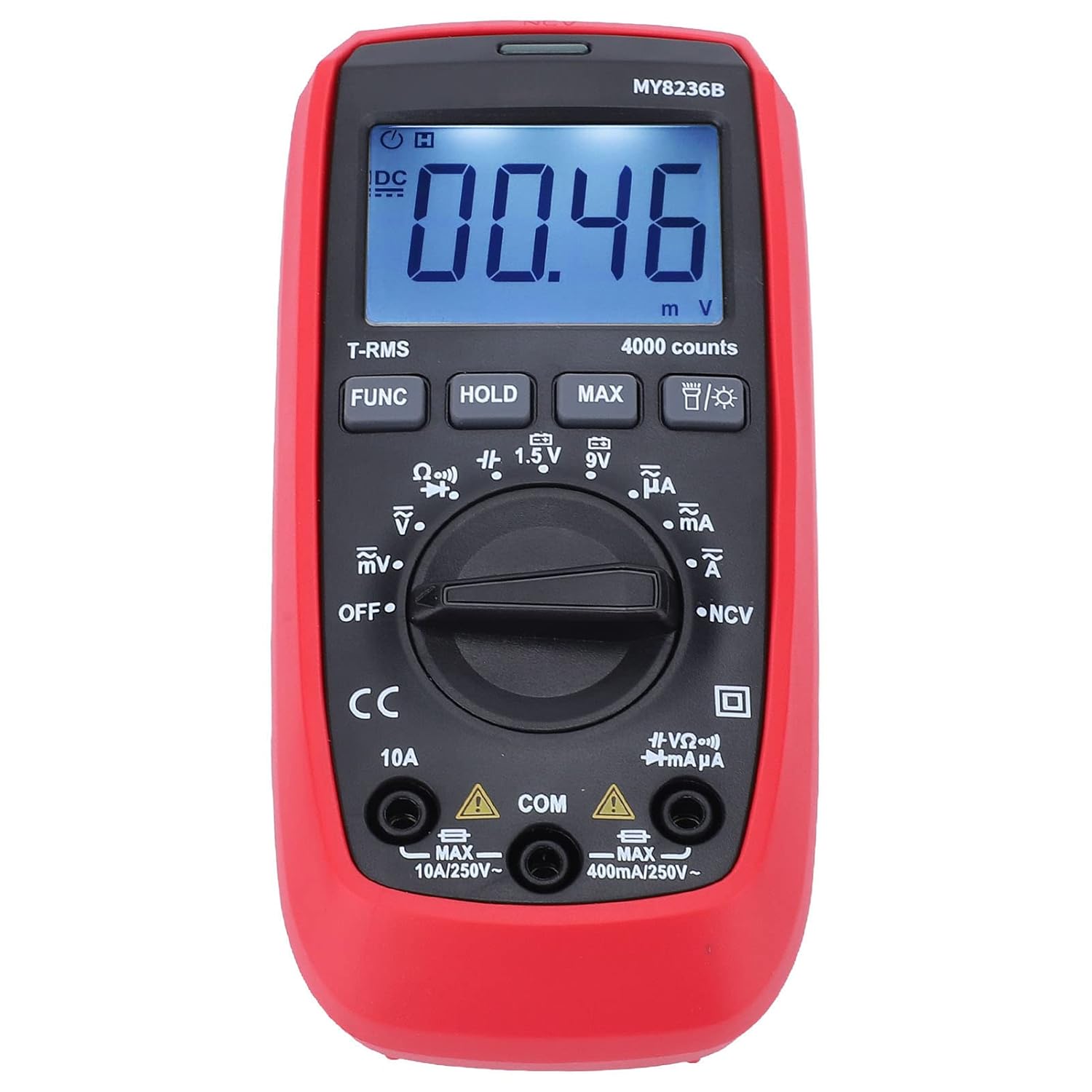
Image: Front view of the Jauarta MY8236B Digital Multimeter, highlighting the central rotary switch for function selection and the digital display.
5.2 Measuring DC Voltage (V–)
- Set the rotary switch to the 'V–' range. Select an appropriate range (e.g., 4V, 40V, 400V) higher than the expected voltage. If the voltage is unknown, start with the highest range and decrease as needed.
- Connect the red test lead to the positive (+) side of the circuit and the black test lead to the negative (-) side.
- Read the voltage value on the display.
5.3 Measuring AC Voltage (V∼)
- Set the rotary switch to the 'V∼' range. Select an appropriate range higher than the expected voltage.
- Connect the test leads across the AC voltage source.
- Read the voltage value on the display.
5.4 Measuring DC Current (A–)
Caution: Never connect the multimeter in parallel with a voltage source when measuring current. Always connect it in series with the load. Ensure the correct input jack (VΩmA or 10A) is used.
- Turn off power to the circuit.
- Break the circuit at the point where current is to be measured.
- Set the rotary switch to the 'A–' range (e.g., µA, mA, or 10A).
- Connect the red test lead to the appropriate current input jack (VΩmA for up to 400mA, 10A for up to 10A).
- Connect the multimeter in series with the circuit.
- Restore power to the circuit and read the current value.
5.5 Measuring AC Current (A∼)
Follow the same safety precautions and connection method as for DC current, but set the rotary switch to the 'A∼' range.
5.6 Measuring Resistance (Ω)
Caution: Ensure the circuit is de-energized before measuring resistance. Do not measure resistance on a live circuit.
- Turn off power to the circuit or component.
- Set the rotary switch to the 'Ω' range.
- Connect the test leads across the component or circuit to be measured.
- Read the resistance value on the display.
5.7 Special Functions
- FUNC Button: Used to switch between different functions within a single rotary switch position (e.g., AC/DC, Diode/Continuity).
- HOLD Button: Freezes the current reading on the display. Press again to release.
- MAX Button: Displays the maximum measured value.
- Backlight Button: Activates or deactivates the display backlight for better visibility in low-light conditions.
6. Maintenance
6.1 Cleaning
To maintain accuracy and prevent damage, keep the multimeter clean and dry. Wipe the case with a damp cloth and mild detergent. Do not use abrasives or solvents. Ensure no moisture enters the meter.
6.2 Battery Replacement
When the battery indicator appears on the display, replace the batteries promptly to ensure accurate readings. Refer to Section 4.1 for battery installation instructions.
6.3 Storage
If the multimeter is not used for an extended period, remove the batteries to prevent leakage and damage. Store the instrument in a cool, dry place away from direct sunlight and extreme temperatures.
7. Troubleshooting
- No Display: Check if the batteries are correctly installed and have sufficient charge. Replace batteries if necessary. Ensure the rotary switch is not in the 'OFF' position.
- Incorrect Readings: Verify that the test leads are properly connected to the correct input jacks and that the rotary switch is set to the appropriate function and range. Ensure the circuit is de-energized for resistance measurements.
- No Reading for Current: Check if the fuse is blown. If measuring high current, ensure the red lead is in the 10A jack.
- Display Shows 'OL' (Overload): The measured value exceeds the selected range. Switch to a higher range or ensure the input is within the meter's maximum specifications.
8. Specifications
| Parameter | Range |
|---|---|
| DC Voltage | 400mV, 4V, 40V, 400V, 600V |
| AC Voltage | 400mV, 4V, 40V, 400V, 600V |
| DC Current | 400µA, 4000µA, 40mA, 400mA, 10A |
| AC Current | 400µA, 4000µA, 40mA, 400mA, 10A |
| Resistance | 400Ω, 4kΩ, 40kΩ, 400kΩ, 4MΩ, 40MΩ |
| Display Count | 4000 counts |
| Battery Type | 2 x 1.5V AAA battery |
| Material | ABS |
| Item Weight | 323 g |
| Parcel Dimensions | 16 x 11 x 5 cm |
9. Safety Information
- Always inspect the multimeter and test leads for any damage before use. Do not use if damaged.
- Do not apply voltage or current that exceeds the maximum rated input for any range.
- Use caution when working with voltages above 30V AC RMS, 42V peak, or 60V DC. These voltages pose a shock hazard.
- Always disconnect the test leads from the circuit before changing functions or ranges.
- Do not operate the meter in explosive gas, vapor, or dusty environments.
- Ensure your hands are dry when operating the meter.
10. Warranty and Support
For warranty information or technical support, please refer to the documentation provided with your purchase or contact Jauarta customer service through your retailer. Keep your purchase receipt as proof of purchase.