1. Introduction
This manual provides detailed instructions for the safe and effective use of the Telituny VC850A+ Phase Sequence Tester. This device is designed for electricians and installation professionals to accurately determine phase sequence, detect phase loss, and measure voltage in three-phase electrical systems.
The VC850A+ is a compact, durable, and precise instrument, meeting Cat III 600V safety standards. It features a clear LCD display for real-time results and is equipped with automatic shut-off and low voltage alerts to ensure safe operation.
2. Safety Information
Always adhere to the following safety guidelines to prevent injury or damage to the instrument:
- This 3-phase sequence tester meets Cat III 600V safety standards.
- Operate the device only under the direct supervision of an adult, especially in professional environments.
- Ensure proper battery installation before use.
- Always connect the test leads correctly to the three-phase input terminals (yellow to L1/A, green to L2/B, red to L3/C).
- Do not exceed the working voltage range of 40-600V.
- The device includes automatic shut-off and low voltage alerts for enhanced safety.
- Built-in guards ensure safe operation when checking motor wiring and power systems.
- Regularly inspect test leads and the instrument for any signs of damage. Do not use if damaged.

Image Description: A multilingual warning sign stating "WARNING: To be used under the direct supervision of an adult." in English, French, Spanish, Italian, and German.
3. Product Overview and Components
The Telituny VC850A+ Phase Sequence Tester is a handheld device designed for ease of use and portability. It consists of the main unit, three test leads with alligator clips, and a storage box.

Image Description: The Telituny VC850A+ Phase Sequence Tester, a teal-colored rectangular device, is shown with its three attached test leads (yellow, green, red) ending in probes. A black storage pouch and three additional alligator clips are also visible. The device's LCD screen displays "LLL" and a rotation arrow.
3.1 Key Components

Image Description: A diagram illustrating the components of the VC850A+ tester. Numbered labels point to: (1) Measurement connection line, (2) LCD display, (3) Forward and reverse phase sequence indicator, (4) Yellow corresponds to L1/A phase, (5) Green corresponds to L2/B phase, (6) Red corresponds to L3/C phase, (7) Test clip.
- Measurement Connection Lines: The integrated yellow, green, and red cables used for connecting to the electrical system.
- LCD Display: A 3-digit LCD screen with 18mm word height for displaying measurement results and indicators.
- Phase Sequence Indicator: An arrow icon on the LCD display indicating forward or reverse phase rotation.
- L1/A Phase Connection (Yellow): Input terminal for the first phase.
- L2/B Phase Connection (Green): Input terminal for the second phase.
- L3/C Phase Connection (Red): Input terminal for the third phase.
- Test Clips (Alligator Clips): Detachable clips for secure connection to test points.
4. Specifications
| Feature | Specification |
|---|---|
| Model | VC850A+ |
| Material | ABS |
| Display | 3-digit LCD, 18mm word height |
| Sampling Rate | 3 times/second |
| Working Voltage Range | 40-600V |
| Working Environment Temperature | 0-40℃ |
| Working Environment Humidity | 0-80%Rh |
| Storage Environment Temperature | -10-60℃ |
| Storage Environment Humidity | 0-85%Rh |
| Power Supply | 3 x AAA batteries |
| Instrument Size | Approx. 116 x 66 x 26 mm (4.57 x 2.6 x 1.02 inches) |
| Line Length | Approx. 800 mm (31.5 inches) |
| Weight | 290 g |
| Safety Standard | CAT III 600V |

Image Description: A visual representation of the Telituny VC850A+ Phase Sequence Tester with its dimensions labeled: Instrument Size: Approx. 116 x 66 x 26mm / 4.57 x 2.6 x 1.02in, and Line Length: Approx. 800mm / 31.5in.
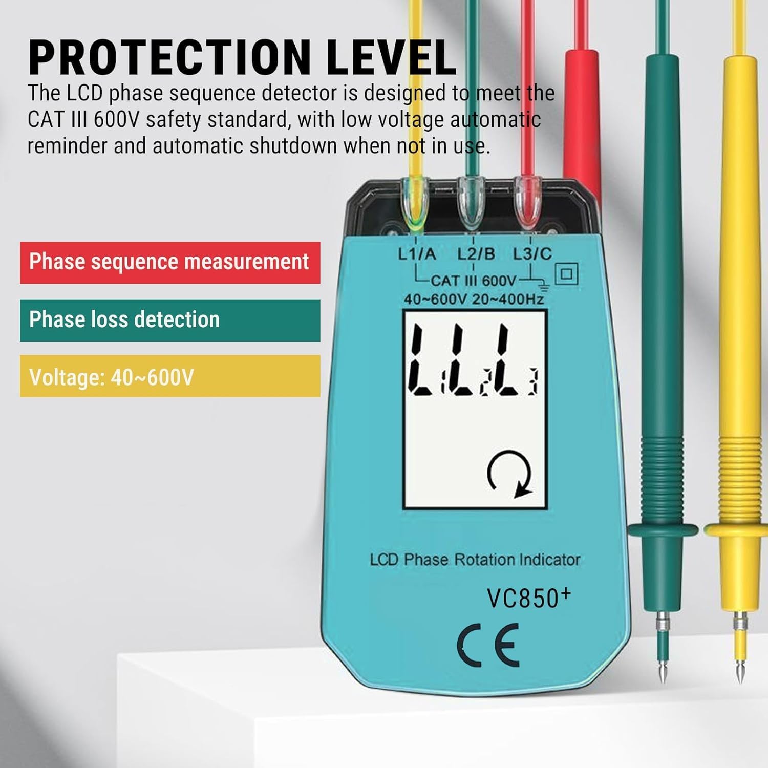
Image Description: A graphic highlighting the protection level of the VC850A+ tester. It states that the LCD phase sequence detector meets the CAT III 600V safety standard, with low voltage automatic reminder and automatic shutdown when not in use. It also indicates phase sequence measurement, phase loss detection, and voltage range of 40-600V.
5. Setup
- Battery Installation: Open the battery compartment on the back of the device and insert 3 x AAA batteries, ensuring correct polarity. Close the compartment securely.
- Connect Test Leads: The test leads are permanently attached to the instrument. Ensure they are not damaged or frayed.
- Attach Alligator Clips: Securely attach the provided alligator clips to the probes of the yellow, green, and red test leads if needed for your application.
6. Operating Instructions
The VC850A+ is designed for straightforward operation. Follow these steps to perform measurements:
- Power On: The device automatically powers on when connected to a live three-phase circuit within its operating voltage range.
- Connect to Circuit: After installing the battery correctly, reliably connect the yellow, green, and red three-phase input terminals of the instrument to the three-phase electrical test terminals respectively.
- Connect the Yellow lead to the L1/A phase.
- Connect the Green lead to the L2/B phase.
- Connect the Red lead to the L3/C phase.
- Read Display: Observe the LCD display for the phase sequence indication.
6.1 Interpreting Results

Image Description: Two LCD display examples. The left display shows "LLL" with a clockwise rotating arrow, indicating a forward phase sequence. The right display shows "LLL" with a counter-clockwise rotating arrow, indicating a reverse phase sequence.
- Forward Phase: When the three-phase electricity being measured is in the forward phase, the LCD displays "LLL" with a clockwise rotating arrow.
- Reverse Phase: When the three-phase electricity being measured is in the reverse phase, the LCD displays "LLL" with a counter-clockwise rotating arrow.
- Phase Loss/Open Circuit: If one or more phases are missing or an open circuit is detected, the display will indicate the missing phase(s) (e.g., "LL" with a blank space for the missing phase).

Image Description: A grid of five LCD display examples. The top row shows displays for missing phases (e.g., L1 and L2 present, L2 and L3 present, L1 and L3 present). The bottom row shows "LLL" with a clockwise arrow for forward phase and "LLL" with a counter-clockwise arrow for reverse phase.
The device provides instant measurements of the direction of rotation with an accuracy of ±1°.

Image Description: The Telituny VC850A+ Phase Sequence Tester is shown in the foreground, connected via its test leads to an electrical control panel in the background, demonstrating its application in a real-world setting.
7. Maintenance
To ensure the longevity and accuracy of your Telituny VC850A+ Phase Sequence Tester, follow these maintenance guidelines:
- Cleaning: Wipe the instrument with a dry, soft cloth. Do not use abrasive cleaners or solvents.
- Storage: Store the device in its provided storage box in a cool, dry place, away from direct sunlight and extreme temperatures. Refer to storage environment specifications.
- Battery Replacement: Replace batteries promptly when the low voltage alert is displayed to ensure accurate readings and prevent damage from battery leakage.
- Inspection: Periodically inspect the test leads and the main unit for any physical damage, cracks, or frayed insulation. Discontinue use if damage is found.
8. Troubleshooting
If you encounter issues with your VC850A+ tester, consider the following common troubleshooting steps:
- No Display/Device Not Turning On:
- Check if batteries are correctly installed and have sufficient charge. Replace if necessary.
- Ensure the device is connected to a live three-phase circuit within the 40-600V operating range.
- Incorrect Phase Indication:
- Verify that the test leads are connected to the correct phases (Yellow to L1/A, Green to L2/B, Red to L3/C).
- Ensure good contact between the test clips and the test points.
- Inconsistent Readings:
- Check for loose connections.
- Ensure the operating environment temperature and humidity are within specified ranges.
- Low Voltage Alert:
- Replace the AAA batteries immediately.
If problems persist after attempting these steps, contact customer support.
9. Warranty and Support
For warranty information or technical support, please refer to the documentation provided at the time of purchase or contact Telituny customer service through their official channels. Keep your purchase receipt as proof of purchase.