
1. Introduction
This manual provides essential information for the safe and efficient operation of your EcoSolLi 6500W Solar Hybrid Inverter. This all-in-one unit combines a solar inverter, AC charger, and MPPT solar charge controller, designed for reliable power conversion for home and RV applications. Please read this manual thoroughly before installation and use.
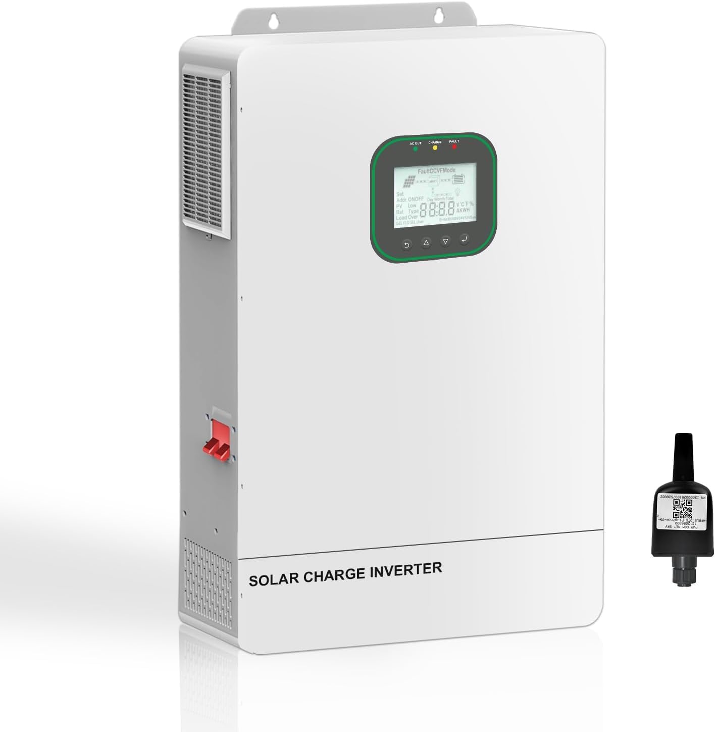
Figure 1: EcoSolLi 6500W Solar Hybrid Inverter. This image displays the main unit of the inverter along with a separate WiFi module, highlighting its compact design and connectivity feature.
2. Safety Instructions
Adherence to these safety guidelines is crucial for preventing injury and damage to the inverter. Keep this manual for future reference.
- Installation must be performed by qualified personnel.
- Ensure all wiring complies with local and national electrical codes.
- Do not disassemble the inverter. There are no user-serviceable parts inside.
- Avoid contact with water or other liquids.
- Ensure proper ventilation around the inverter to prevent overheating.
- Disconnect all power sources (solar, battery, AC) before performing any maintenance or wiring.
- Wear appropriate personal protective equipment (PPE) during installation and maintenance.

Figure 2: Comprehensive Protection Features. This diagram illustrates the various built-in safety mechanisms of the inverter, including short circuit, over-voltage, overcurrent, undervoltage, backflow, overheating, overload, and overcharge protection.
3. Product Features
The EcoSolLi 6500W Solar Hybrid Inverter is equipped with advanced features for optimal performance and reliability:
- Pure Sine Wave Output: Ensures compatibility with sensitive electronics and appliances.
- Advanced SPWM Technology: For stable and efficient power conversion.
- Dual Closed-Loop Control: Enhances system stability and performance.
- Built-in MPPT Solar Charge Controller: Maximizes energy harvest from solar panels with up to 99% efficiency.
- 360° Comprehensive Protection: Safeguards against short circuits, over/under voltage, overloads, reverse polarity, and includes dust-proof protection.
- Smart LCD Display: Provides real-time system data and operating status.
- Customizable Settings: Adjust battery charging current, AC/solar charging priority, and load current preferences via the LCD menu.
- Remote Monitoring: Supports WIFI/GPRS for monitoring inverter status via an app (module sold separately).
- Flexible Charging Modes: Solar Only, Mains Priority, Solar Priority, Mains & Solar Hybrid Charging.
- Flexible Output Modes: Mains Bypass, Inverter Output.
- Battery Compatibility: Supports 48V Lead-Acid (Sealed, AGM, Gel, Flooded) and Lithium batteries.
- Parallel Operation: Up to 6 units can be connected in parallel for increased capacity (up to 72KW for 120V systems).
- Split-Phase Configuration: Supports series and parallel connections for 240V and 120V systems.

Figure 3: All-in-One Hybrid Solar Inverter Charger. This image highlights key specifications such as Max. PV Input Power (4500W x 2), Max. PV Charge Current (150A), Max. PV Open Circuit Voltage (300VDC), and MPPT Voltage Range (90-260Vdc).
4. Setup and Installation
Proper installation is critical for the inverter's performance and safety. Consult a qualified electrician for installation.
4.1. Site Selection
- Install the inverter in a well-ventilated area, away from direct sunlight, heat sources, and moisture.
- Ensure sufficient clearance around the unit for airflow.
- Mount the inverter vertically on a sturdy surface.
4.2. Wiring Connections
Follow these steps for wiring. Always ensure all power sources are disconnected before making connections.
- Battery Connection: Connect the battery bank (48V) to the inverter's battery terminals. Ensure correct polarity.
- Solar Panel Connection: Connect the solar panel array to the PV input terminals. Observe correct polarity and voltage limits.
- AC Input Connection: Connect the AC utility grid power to the AC input terminals.
- AC Output Connection: Connect your loads (appliances, home circuits) to the AC output terminals.
- Grounding: Ensure the inverter is properly grounded according to local electrical codes.

Figure 4: Typical Wiring Diagram. This diagram illustrates the connections between solar panels, the inverter, battery bank, utility grid, and household loads. It shows PV power (4500W*2), battery type (48V lead-acid/lithium), Max. Battery Charging Current (120A), Rated Output Power (6500W), and Input Voltage Range (90-140Vac).
4.3. Parallel and Split-Phase Configuration
The inverter supports parallel connection for increased power output and split-phase configurations for various residential applications.

Figure 5: Versatile Design for Parallel and Split-Phase Connections. This image demonstrates how up to six inverters can be connected in single-phase parallel for 120V systems (up to 72KW) or in series and parallel for split-phase 240V and 120V systems, offering up to 15 different configurations.
- Single-Phase Parallel: Up to 6 units for maximum 72KW power delivery in 120V residential systems.
- Split-Phase: Series and parallel connections for 240V and 120V systems. Refer to the detailed wiring diagrams in the full product manual for specific configurations.
5. Operating Modes and Settings
The inverter offers flexible charging and output modes, configurable via the smart LCD display.
5.1. Charging Priority Settings
Control how the battery bank is charged from different power sources:
- Solar Priority: Solar power is the primary charging source. AC utility will supplement if solar is insufficient.
- Mains Priority (AC Priority): AC utility is the primary charging source. Solar power will supplement if AC is unavailable or insufficient.
- Solar Only: Only solar power is used for charging the batteries.
- Mains & Solar Hybrid Charging: Both AC and solar charge the battery simultaneously.

Figure 6: Charging and Load Priority Settings. This image illustrates the options for charging priority (Solar Priority, Solar and AC Input, Solar Only) and load priority (Solar Priority, AC Priority, DC Priority).
5.2. Load Priority Settings
Control how your appliances receive power:
- Solar Priority (SBU): Solar power first, then battery, then AC utility.
- AC Priority (UTI): AC utility first, then battery, then solar.
- Solfirst (SOL): Solar power first, then AC utility, then battery.
5.3. Battery Compatibility
The inverter is compatible with various 48V battery types:
- Lead-Acid Batteries: Sealed, AGM, Gel, Flooded.
- Lithium Batteries.
- Can operate without a battery, using solar and utility grid to power loads simultaneously.
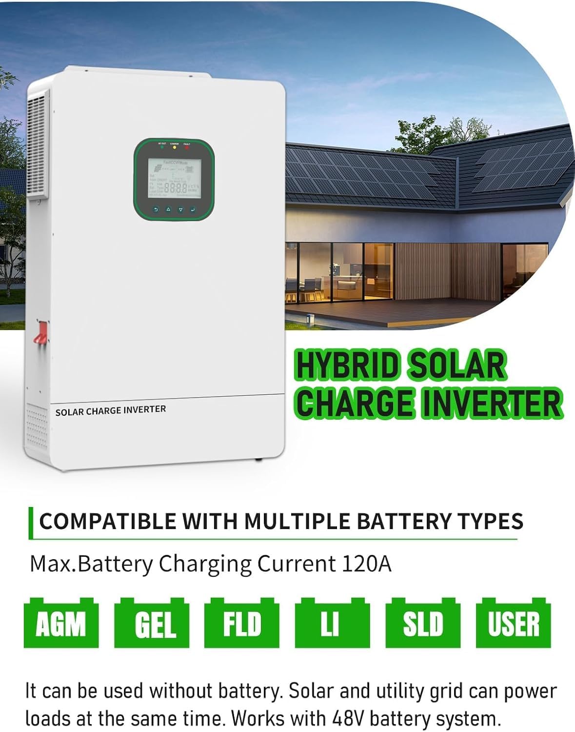
Figure 7: Compatible Battery Types. This image lists the supported 48V battery types: AGM, GEL, FLD (Flooded), LI (Lithium), SLD (Sealed Lead-Acid), and USER-defined settings. It also notes the maximum battery charging current of 120A.
5.4. Real-Time Monitoring
The inverter supports WIFI/GPRS remote monitoring, allowing users to check the inverter status anytime, anywhere via a dedicated application. The Wi-Fi/GPRS data acquisition module must be purchased separately.
6. Technical Specifications
| Parameter | Value |
|---|---|
| Model Number | 6500W |
| Rated Output Power | 6500 watts |
| Input Voltage | 48 Volts (DC) |
| Max. PV Input Power | 4500W x 2 (9000W total) |
| Max. PV Charge Current | 150A |
| Max. PV Open Circuit Voltage | 300VDC |
| MPPT Voltage Range | 90-260Vdc |
| Max. Battery Charging Current | 120A |
| Output Waveform | Pure Sine Wave |
| Dimensions (Package) | 20 x 18 x 9 inches |
| Item Weight | 54 pounds |
| Manufacturer | EcoSolLi |
7. Maintenance
Regular maintenance ensures the longevity and optimal performance of your inverter.
- Cleaning: Periodically clean the exterior of the inverter with a dry cloth. Ensure ventilation openings are free from dust and debris.
- Connections: Annually check all electrical connections for tightness and signs of corrosion.
- Battery Inspection: If using lead-acid batteries, check electrolyte levels and terminal conditions as per battery manufacturer guidelines.
- Environment: Ensure the installation environment remains within specified temperature and humidity ranges.
8. Troubleshooting
This section provides guidance for common issues. For complex problems, contact technical support.
| Problem | Possible Cause | Solution |
|---|---|---|
| Inverter not turning on | No battery power; DC breaker open; loose connections. | Check battery voltage; ensure DC breaker is closed; verify all connections are secure. |
| No AC output | Overload; short circuit; AC breaker open; inverter fault. | Reduce load; check for short circuits; close AC breaker; check LCD for error codes. |
| Low solar charging | Shaded panels; dirty panels; incorrect PV wiring; low sunlight. | Clear shading; clean panels; verify PV connections and voltage; wait for better sunlight. |
| Overheating warning | Insufficient ventilation; high ambient temperature; blocked fan. | Ensure adequate airflow; move to a cooler location; clean fan vents. |
9. Warranty and Support
For warranty information and technical support, please refer to the documentation provided with your purchase or contact EcoSolLi customer service. Ensure you have your product model number and purchase date available when contacting support.
Manufacturer: EcoSolLi