1. Introduction
The Wonrabai ESP32-S3 1.85-inch Round Touch LCD Development Board is a versatile microcontroller development platform. It features an ESP32-S3 chip, a 1.85-inch round capacitive touch LCD, and integrated audio input/output capabilities. This board is designed for applications requiring AI interaction, offline voice control, and can function as a smart speaker box.
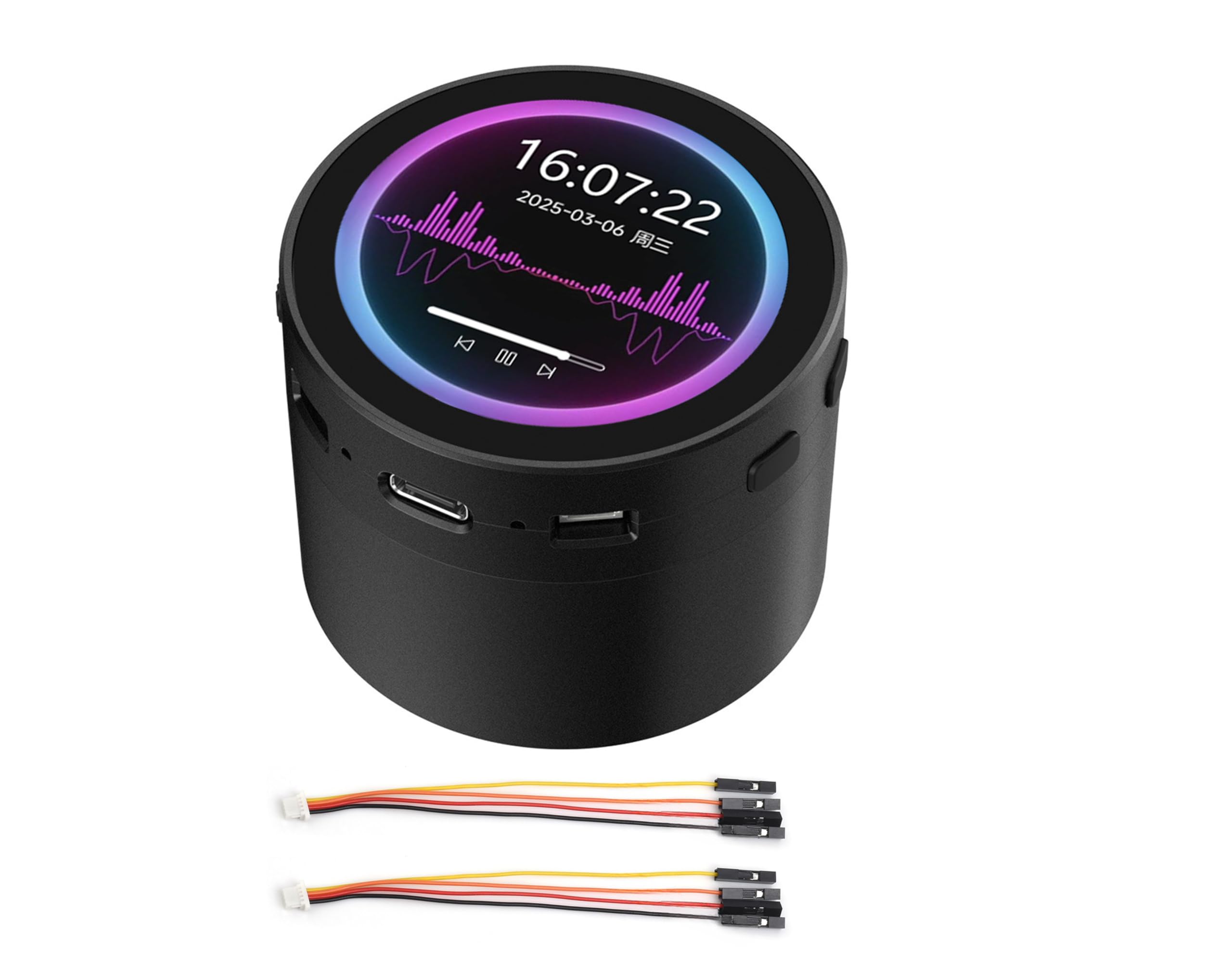
Image 1.1: The ESP32-S3 Development Board with its integrated speaker box.
Product Overview
This development board integrates several key functionalities:
- ESP32-S3 Microcontroller: High-performance Xtensa 32-bit LX7 dual-core processor, up to 240MHz.
- Wireless Connectivity: Supports 2.4GHz Wi-Fi (802.11 b/g/n) and Bluetooth 5 (LE) with an onboard antenna.
- Memory: Built-in 512KB SRAM, 384KB ROM, with onboard 16MB Flash and 8MB PSRAM.
- Display: 1.85-inch capacitive touch LCD with 360x360 resolution and 262K colors, suitable for GUI applications like LVGL.
- Audio: Integrated audio input and output, including an 8Ω 2W speaker and microphone, enabling AI interaction and offline voice control.
- Peripherals: Supports expansion via UART, I2C, and GPIO interfaces. Includes an audio decoder, RTC sensor, TF card slot, and battery recharge management module.
2. Key Features
The ESP32-S3 1.85-inch Round Touch LCD Development Board offers a robust set of features for various embedded projects:
- High-Performance Processor: Equipped with an Xtensa 32-bit LX7 dual-core processor, operating at up to 240MHz.
- Integrated Wireless: Features 2.4GHz Wi-Fi (802.11 b/g/n) and Bluetooth 5 (LE) for versatile connectivity.
- Ample Memory: Includes 512KB SRAM, 384KB ROM, 16MB Flash, and 8MB PSRAM for application and data storage.
- Capacitive Touch LCD: A 1.85-inch round display with 360x360 resolution and 262K colors, supporting smooth GUI programs and flexible touch interaction via I2C interface with interrupt support.
- Audio Capabilities: Onboard audio input/output with a microphone and speaker, supporting high-quality audio processing and customizable shortcut commands for offline voice control.
- AI Speech Interaction: Allows access to online large model platforms such as GPT, DeepSeek, and Doubao for advanced AI functionalities.
- Multiple Peripherals: Expandable via UART, I2C, and GPIO interfaces. Includes an onboard audio decoder, RTC sensor, TF card slot, and battery recharge management module.
- Power Management: Supports accurate clock control and multiple power modes for low power consumption in various scenarios.

Image 2.1: Overview of the board's core features and capabilities.
3. Product Versions
The ESP32-S3 1.85-inch Round Touch LCD Development Board is available in two main versions, both featuring touch functionality:
- Standard Version (ESP32-S3-Touch-LCD-1.85C): This version includes the core development board with the 1.85-inch round touch LCD.
- With Speaker Box Version (ESP32-S3-Touch-LCD-1.85C-BOX): This version includes the standard board integrated into a speaker box, providing enhanced audio capabilities and a compact enclosure. It is designed for applications requiring integrated sound output and a more finished product appearance. This version also supports an optional 3.7V Lithium battery.

Image 3.1: Comparison of the Standard Version and the With Speaker Box Version.
4. Hardware Overview
This section details the components and interfaces available on the ESP32-S3 Development Board.

Image 4.1: Numbered components on the ESP32-S3 Development Board.
Component Identification
| No. | Component | Description |
|---|---|---|
| 1 | ESP32-S3R8 | Dual-core processor, up to 240MHz operating frequency |
| 2 | 16MB Flash | Onboard flash memory |
| 3 | TCA9554PWR | GPIO expander chip |
| 4 | RTC chip (PCF85063) | Real-Time Clock chip |
| 5 | Amplifier chip | Audio amplifier |
| 6 | PCM5101 audio decoder | Audio digital-to-analog converter |
| 7 | Battery recharge manager | Manages battery charging |
| 8 | MP1605GTF-Z | Power module, supports up to 3.3V 2A output |
| 9 | Volume adjustment knob | Controls audio output volume |
| 10 | TF card slot | For microSD card storage |
| 11 | IPEX1 connector | For external antenna (requires resoldering onboard resistor) |
| 12 | Onboard ceramic antenna | Integrated antenna for Wi-Fi/Bluetooth |
| 13 | Battery power supply ON/OFF | Switch for battery power |
| 14 | Speaker header | Connection for external speaker |
| 15 | Microphone | Onboard microphone for audio input |
| 16 | MX1.25 battery header | MX1.25 2PIN connector for 3.7V Lithium battery, supports charging and discharging |
| 17 | UART header | Serial communication interface |
| 18 | Power indicator | LED indicating power status |
| 19 | USB Type-C port | For power supply and data communication |
| 20 | Charge indicator | LED indicating battery charge status (lights up when charging, off when fully charged; status uncertain if battery not connected) |
| 21 | I2C header | For I2C peripherals; connects with internal chip, but only supports I2C peripherals and cannot be mapped to other functions. |
| 22 | RTC battery header | For connecting a rechargeable RTC battery |
| 23 | 1.27mm pin header | Reserved 28PIN header, adapting GPIO and other function pins |
| 24 | RESET button | Resets the board |
| 25 | BOOT button | Enters bootloader mode |
5. Setup Guide
5.1 Power Connection
Connect the development board to a power source using the USB Type-C port (19). This port also facilitates data communication for programming and debugging.
5.2 Peripheral Connections
Utilize the UART header (17), I2C header (21), and the 1.27mm pin header (23) to connect external peripherals as required by your application. Refer to the pinout diagram for specific GPIO assignments.
5.3 Battery Installation (For Speaker Box Version)
For portable operation, connect a 3.7V Lithium battery to the MX1.25 battery header (16). Ensure correct polarity. The battery recharge manager (7) will handle charging when the board is powered via USB-C. The charge indicator (20) will illuminate during charging.
5.4 TF Card Installation
Insert a microSD card into the TF card slot (10) for additional storage. Ensure the card is inserted correctly until it clicks into place.
6. Operating Instructions
6.1 Display and Touch Interface
The 1.85-inch round LCD provides visual output. Interact with the device using the capacitive touch screen. The touch function supports flexible operation and smooth UI interaction, with interrupt support for responsive feedback.
6.2 Audio Input and Output
The board features an integrated microphone (15) for audio input and an onboard speaker for audio output. Adjust the volume using the volume adjustment knob (9).

Image 6.1: Audio input for voice commands and audio playback demonstration.
6.3 AI Speech Interaction
The board supports AI speech interaction, allowing access to online large model platforms such as GPT, DeepSeek, and Doubao. This enables advanced conversational and analytical capabilities.

Image 6.2: AI speech interaction process with online platforms.
6.4 Offline Voice Control
Equipped with a provided offline voice model, the device can realize control via customizable shortcut commands without requiring an internet connection.
6.5 Reset Function
Press the RESET button (24) to restart the development board. The BOOT button (25) is used to enter bootloader mode for firmware flashing.
7. Application Scenarios
The ESP32-S3 Development Board is suitable for a variety of applications:

Image 7.1: Potential application scenarios for the development board.
- Multiple Outputs: Can be used as an information output unit in both display and audio, allowing users to design projects based on their needs for information interaction in image and audio.
- Multiple Inputs: Supports touch, button, and voice recognition inputs, enabling users to design projects requiring diverse input methods for equipment control.
- Human-Machine Interface (HMI): The human-machine interface facilitates interaction and information exchange between the system and the user, transforming internal data into a human-understandable format.
- LVGL GUI Development: LVGL is a free, open-source graphics library that provides tools for creating embedded GUIs with graphical elements, visual effects, and low memory requirements.
8. Technical Specifications
Detailed specifications for the ESP32-S3 Development Board:
| Feature | Specification |
|---|---|
| Processor | Xtensa 32-bit LX7 dual-core, up to 240MHz |
| Wireless Connectivity | 2.4GHz Wi-Fi (802.11 b/g/n), Bluetooth 5 (LE) |
| Onboard Memory | 512KB SRAM, 384KB ROM, 16MB Flash, 8MB PSRAM |
| Display | 1.85-inch Round Capacitive Touch LCD, 360x360 resolution, 262K color |
| Audio | Integrated audio input/output, 8Ω 2W Speaker, Microphone, Audio Decoder |
| Interfaces | UART, I2C, GPIO, USB Type-C |
| Storage | TF card slot |
| Power Management | Battery recharge management module, low power modes |
| RTC | PCF85063 RTC chip with battery header |
| Item Model Number | ESP32-S3-Touch-LCD-1.85C-BOX-EN |
| Package Dimensions | 4.45 x 3.27 x 2.8 inches |
| Item Weight | 9.2 ounces |
8.1 Outline Dimensions
The following diagrams provide the physical dimensions of both the standard and speaker box versions of the development board.
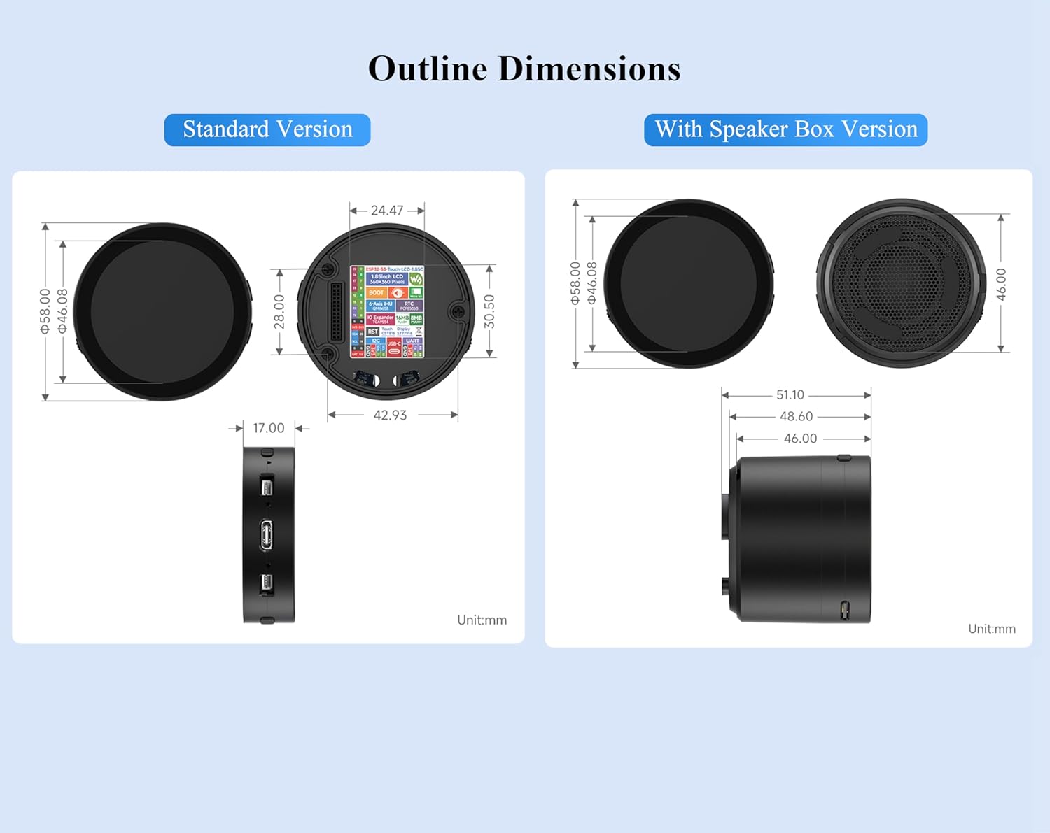
Image 8.1: Outline dimensions for Standard and With Speaker Box versions (Unit: mm).
9. Troubleshooting
This section addresses common issues you might encounter with the ESP32-S3 Development Board.
- No Power/Display:
- Ensure the USB Type-C cable is securely connected to a functional power source.
- If using a battery, verify it is charged and correctly connected to the MX1.25 header, and the battery power switch is ON.
- Check the power indicator LED (18) for activity.
- Touch Screen Unresponsive:
- Ensure the board is powered correctly.
- A firmware issue might be present. Try reflashing the firmware.
- Ensure no physical obstructions are on the screen.
- Voice Control Not Responding:
- Verify the microphone (15) is not obstructed.
- For online AI interaction, ensure a stable Wi-Fi connection.
- For offline voice control, confirm that the correct offline voice model is loaded and configured.
- Connectivity Issues (Wi-Fi/Bluetooth):
- Check your code for correct Wi-Fi/Bluetooth initialization and credentials.
- Ensure the onboard ceramic antenna (12) is not damaged or obstructed.
- If using an external antenna, verify it is properly connected to the IPEX1 connector (11) and the onboard resistor has been resoldered as required.
- General Software/Firmware Issues:
- Refer to the online tutorial and development resources for detailed programming guides and examples. The online tutorial usage guide and development resources can be found at: n9.cl/s4tlg.
- Use the BOOT button (25) to enter bootloader mode for flashing new firmware.
10. Package Contents
The following items are included in your product package:

Image 10.1: Contents of the product package.
- ESP32-S3-Touch-LCD-1.85C-BOX x1
- SH1.0 4PIN cable ~100mm x2
11. Warranty and Support
11.1 Return Policy
This product is eligible for a 30-day return for refund or replacement, subject to the retailer's terms and conditions.
11.2 Online Resources and Support
For comprehensive tutorials, development guides, and additional support, please refer to the official online resources:
- Online Tutorial Usage Guide and Development Resources: n9.cl/s4tlg
For further assistance, please contact your retailer or the manufacturer, Wonrabai, through their official support channels.