1. Introduction
Thank you for choosing the briidea Proportional Trailer Brake Controller BR-162. This digital electric brake control system is designed to provide smooth, reliable, and safe braking for your trailer. Featuring a user-friendly rotary knob and an LCD display, it allows for precise adjustment of braking force, ensuring optimal performance across various towing conditions. This manual provides essential information for proper installation, operation, and maintenance of your brake controller.
The BR-162 is compatible with a wide range of vehicles and supports 1 to 4 braked axles (2 to 8 brakes), making it suitable for utility trailers, RVs, cargo trailers, and boat trailers.
2. Safety Information
Read all instructions carefully before installation and operation. Failure to follow these instructions may result in property damage, personal injury, or death. Keep this manual for future reference.
- Always ensure the brake controller is correctly installed and functioning before towing.
- Perform a test drive in a safe, open area to verify proper brake controller operation and adjustment.
- Do not attempt to adjust the brake controller while driving in heavy traffic or hazardous conditions.
- Regularly inspect all wiring and connections for wear or damage.
- Ensure your vehicle's electrical system can support the brake controller's power requirements.
- Consult a qualified technician if you are unsure about any installation or operation steps.
3. Package Contents
Verify that all items are present before beginning installation:
- briidea Proportional Trailer Brake Controller Main Module
- Rotary Knob with LCD Display
- Wiring Harness
- Mounting Hardware (screws, adhesive pads)
- User Manual (this document)
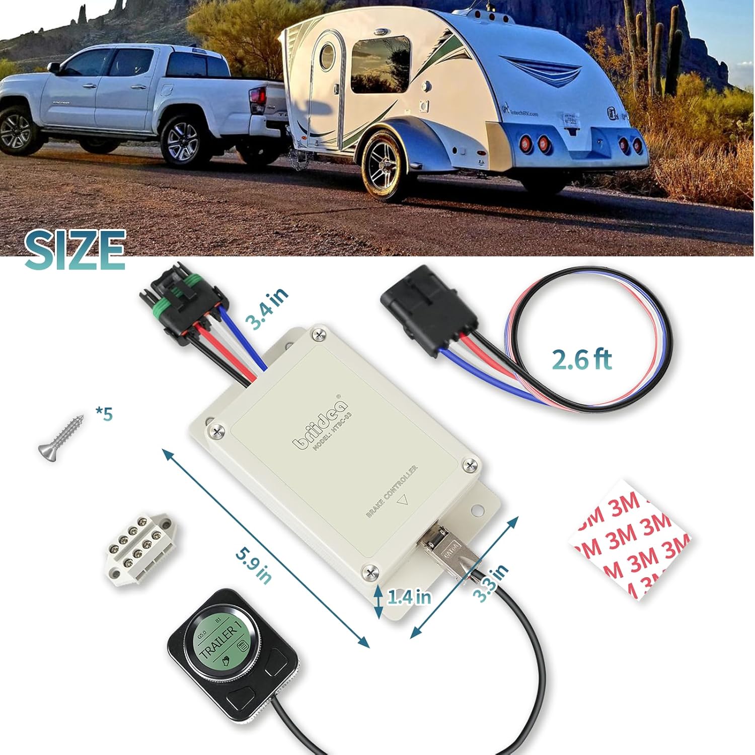
Figure 3.1: Included components and dimensions. The main module measures approximately 5.9 inches in length, 3.4 inches in width, and 1.4 inches in height. The wiring harness is approximately 2.6 feet long. Mounting screws and adhesive pads are also included.
4. Installation
4.1 Mounting the Main Module
The main module should be securely mounted in a location within the vehicle that is protected from moisture and excessive heat. Ensure it is mounted horizontally and parallel to the direction of travel for accurate motion sensing. Use the provided screws or other suitable fasteners to secure the module.
4.2 Mounting the Rotary Knob Display
The rotary knob with LCD display is designed for flexible installation in your vehicle's interior. Choose a location that is easily accessible to the driver and does not obstruct airbags or vehicle controls. The knob can be mounted using the provided adhesive pads.

Figure 4.1: Example placement of the rotary knob display in a vehicle's interior, typically near the dashboard or console for easy access.

Figure 4.2: The back of the rotary knob display features adhesive for secure mounting to a clean, flat surface.
4.3 Wiring Connections
Proper wiring is crucial for the safe and effective operation of the brake controller. Refer to your vehicle's owner's manual or a qualified automotive technician for specific wiring harness locations. The briidea BR-162 uses a standard 4-wire connection:
- Black Wire: Connect to Vehicle Power (12V constant, fused 30A).
- Red Wire: Connect to Stop Light Switch (activates when brake pedal is pressed).
- White Wire: Connect to Vehicle Ground.
- Blue Wire: Connect to Trailer Brakes (output to trailer brake circuit).
Ensure all connections are secure and insulated to prevent short circuits. A 30A auto-reset circuit breaker (not supplied) is recommended for the main power line (Black Wire) to protect the system.
5. Operation
The briidea BR-162 features an intuitive rotary knob and LCD display for easy control and monitoring.
5.1 Initial Setup and Gain Adjustment

Figure 5.1: The LCD display provides real-time information on gain output and boost level.
- Power On: The unit powers on automatically when the vehicle's ignition is on and a trailer is connected.
- Access Menu: Press the integrated Manual/Menu button on the rotary knob to enter the main menu.
- Trailer Setup: Rotate the knob to select 'TRAILER SETUP' and press the button to confirm. You can configure different trailer profiles if needed.
- Adjust Gain: Rotate the knob to adjust the brake gain (0-10). This controls the amount of braking power sent to the trailer. Start with a lower setting and increase gradually during a test drive until smooth, firm braking is achieved.
- Adjust Boost: Rotate the knob to adjust the Boost mode (B0-B3). Boost mode applies more initial braking power to the trailer, useful for heavier trailers or specific towing conditions.
- Save Settings: Settings are typically saved automatically. Press and hold the Manual/Menu button to return to the main interface.
5.2 Manual Override
To manually apply trailer brakes independently of the tow vehicle's brakes, press the Manual/Menu button on the rotary knob. This can be useful for reducing trailer sway or for testing purposes.

Figure 5.2: The rotary knob allows for quick and precise adjustments to gain and boost settings, as well as manual brake activation.
5.3 Ambient Light and Backlight Adjustment
The controller allows adjustment of ambient light detection and LCD backlight levels for optimal visibility in various lighting conditions. Navigate through the menu using the rotary knob to access these settings.
6. Key Features
6.1 Proportional Braking
The BR-162 utilizes a high-sensitivity motion sensor to dynamically adjust the trailer's braking force in proportion to the tow vehicle's deceleration. This results in smoother, more controlled stops compared to time-based controllers. It helps reduce trailer sway and adapts automatically to uphill or downhill terrain, contributing to extended brake system lifespan.

Figure 6.1: Proportional braking ensures smooth and stable stops, reducing trailer sway and adapting to various terrains.
6.2 Advanced Safety Features
The controller incorporates several built-in safety mechanisms to protect your towing setup:
- Overcurrent Protection: Safeguards the system from excessive electrical current.
- Short-Circuit Prevention: Protects against electrical shorts in the wiring.
- Intelligent Fault Detection: Automatically identifies and alerts the user to wiring or brake system issues, aiding in quick troubleshooting.

Figure 6.2: The BR-162 includes multiple safety features for reliable operation.
6.3 Wide Compatibility
The briidea BR-162 is designed for broad compatibility with various vehicle types and trailers. It supports 1 to 4 braked axles (2 to 8 brakes), making it suitable for a wide range of towing applications, from light utility trailers to heavier RVs and cargo trailers.

Figure 6.3: The controller is compatible with a variety of trailers and vehicles, supporting multiple axle configurations.
7. Maintenance
The briidea BR-162 is designed for minimal maintenance. However, regular checks can ensure continued optimal performance:
- Inspect Wiring: Periodically check all wiring connections for corrosion, fraying, or loose terminals. Ensure all connections are secure.
- Clean Display: Wipe the LCD display and rotary knob with a soft, dry cloth to remove dust and grime. Do not use abrasive cleaners or solvents.
- Module Security: Verify that the main module and rotary knob are still securely mounted and have not come loose due to vehicle vibrations.
- System Check: Before each towing trip, perform a quick system check to ensure the controller powers on and responds to inputs.
8. Troubleshooting
If you encounter issues with your briidea BR-162, refer to the following common problems and solutions:
| Problem | Possible Cause | Solution |
|---|---|---|
| Controller not powering on | No power to the unit; Blown fuse; Loose connection. | Check vehicle's 12V power source and ground connections. Inspect the 30A fuse/circuit breaker. Ensure all wiring is secure. |
| No trailer brakes or weak braking | Incorrect gain setting; Loose trailer brake wire; Trailer brake system fault. | Increase gain setting. Check blue wire connection to trailer brakes. Inspect trailer brake wiring and magnets. The intelligent fault detection may indicate specific issues on the LCD. |
| Trailer brakes lock up | Gain setting too high. | Decrease gain setting. |
| LCD display not working | Loose connection to rotary knob; Unit not powered. | Check the connection between the main module and the rotary knob. Ensure the main unit is receiving power. |
| Trailer sway during braking | Improper gain or boost setting; Improper trailer loading. | Adjust gain and boost settings for smoother braking. Ensure trailer is properly loaded and balanced. |
If the problem persists after attempting these solutions, please contact briidea customer support.
9. Specifications
- Model: BR-162
- Brake Type: Proportional
- Axle Compatibility: 1 to 4 braked axles (2 to 8 brakes)
- Input Voltage: 12V DC
- Max Output Current: 30A (requires 30A fused circuit)
- Control Type: Digital Electric with Rotary Knob & LCD Display
- Safety Features: Overcurrent Protection, Short-Circuit Prevention, Intelligent Fault Detection
- Item Weight: Approximately 1.01 pounds (0.46 kg)
- Package Dimensions: Approximately 7.13 x 3.66 x 3.03 inches (18.1 x 9.3 x 7.7 cm)
10. Warranty and Customer Support
briidea products are manufactured to high-quality standards. For warranty information, technical assistance, or customer support, please refer to the contact information provided with your purchase or visit the official briidea website. Please have your model number (BR-162) and purchase details ready when contacting support.
Online Support: Visit the briidea Store on Amazon