KT08B001H0
AUTEC Radio Remote Control System
Model: KT08B001H0
1. Introduction
This instruction manual provides essential information for the safe and effective operation, setup, and maintenance of the AUTEC Radio Remote Control System, specifically the T8B Transmitting Unit and ACRH11 Receiving Unit. This system is designed for controlling cranes and similar industrial machinery wirelessly. Please read this manual thoroughly before using the product.
2. Safety Information
WARNING: Failure to follow these safety instructions could result in serious injury or death, and damage to equipment.
- Always ensure the system is properly installed and configured by qualified personnel.
- Before operation, verify that all safety functions, including the Emergency Stop (EMS) and General Safe Stop (GSS), are fully functional.
- Never operate the remote control system if you are under the influence of alcohol, drugs, or medication that impairs your judgment or physical abilities.
- Keep the transmitting unit dry and clean. Avoid exposure to extreme temperatures, moisture, or corrosive substances.
- Disconnect power source and wait 10 seconds before opening the receiving unit for any maintenance or inspection.
- Only use original AUTEC replacement parts and accessories, especially batteries and chargers.
- Regularly inspect the transmitting unit, receiving unit, and all cables for signs of wear, damage, or loose connections.
- In case of malfunction, immediately cease operation and refer to the troubleshooting section or contact qualified service personnel.
3. Components Overview
The AUTEC Radio Remote Control System typically includes the following main components:
3.1. T8B Transmitting Unit
The handheld remote control unit used by the operator to send commands to the crane. It features various control buttons and safety functions.

Image: Front view of the AUTEC T8B Transmitting Unit, showing the yellow casing with black control buttons, including directional arrows, START, AUX, and a red Emergency Stop button at the top.

Image: Rear view of the AUTEC T8B Transmitting Unit, showing the battery compartment, product label with model T8B, type NNH0, S/N LT00077, FCC ID, IC, and a separate rechargeable lithium polymer battery.
3.2. ACRH11 Receiving Unit
The unit installed on the crane or machinery that receives signals from the transmitting unit and translates them into control commands. It is housed in a robust, weather-resistant enclosure.

Image: Front view of the AUTEC ACRH11 Receiving Unit, a clear plastic enclosure revealing internal electronics and a black label detailing model ACRH11, power supply, radio module, RF power, protection degree (IP65), FCC ID, IC, and a QR code with TU ID: T088701.
3.3. Battery Charger and Batteries
A dedicated charger for the rechargeable batteries used in the T8B transmitting unit. The system includes two batteries for continuous operation.
3.4. Heavy Duty Cover + Belt
Protective accessories for the transmitting unit, enhancing durability and ease of carrying.
4. Setup
4.1. Charging Batteries
- Connect the battery charger to a suitable power outlet.
- Insert the rechargeable battery into the charging slot.
- Allow the battery to charge fully before first use. Refer to the charger's indicator lights for charging status.
4.2. Installing Battery in T8B Transmitting Unit
- Ensure the transmitting unit is powered off.
- Locate the battery compartment on the rear of the T8B unit.
- Open the battery compartment cover.
- Insert the charged battery, ensuring correct polarity.
- Securely close the battery compartment cover.
4.3. Mounting and Connecting the ACRH11 Receiving Unit
The ACRH11 receiving unit should be mounted in a secure location on the crane or machinery, protected from excessive vibration and direct impact. Connection to the crane's electrical system should only be performed by a qualified electrician.
- Mount the ACRH11 unit using appropriate hardware, ensuring it is stable and accessible for maintenance.
- Connect the power supply (24-220V~ 50-60Hz, 0.8A) to the designated terminals on the ACRH11.
- Connect the control outputs from the ACRH11 to the crane's control inputs according to the crane's wiring diagram and the ACRH11's connection interfaces (cable gland M20 and M25, plug 16 and 24 pin).
- Ensure all connections are secure and properly insulated.
5. Operating Instructions
5.1. Powering On/Off
- To power on the T8B transmitting unit, press and hold the designated power button (if applicable) or follow the specific power-on sequence.
- The ACRH11 receiving unit will power on automatically when connected to the crane's power supply.
- To power off the T8B transmitting unit, press and hold the power button until the unit shuts down.
5.2. Basic Control Functions
The T8B transmitting unit features various buttons for controlling crane movements:
- Directional Buttons: Used for controlling movement in specific directions (e.g., up/down, left/right, forward/backward).
- START Button: Initiates the control sequence or activates specific functions.
- AUX Button: Used for auxiliary functions, which may vary depending on the crane configuration.
- GSS (General Safe Stop) Button: A safety function that brings the crane to a safe stop.
5.3. Emergency Stop (EMS)
The red Emergency Stop button on the T8B transmitting unit is a critical safety feature. In case of an emergency or unsafe condition, immediately press this button to halt all crane operations. The EMS function is designed to meet SIL 2 / PL d; cat. 3 performance levels.
6. Maintenance
6.1. Battery Care
- Recharge batteries regularly, even if not in constant use, to maintain optimal performance and lifespan.
- Avoid fully discharging batteries.
- Store batteries in a cool, dry place when not in use.
- Replace batteries when their capacity significantly diminishes.
6.2. Cleaning
- Clean the transmitting unit and receiving unit with a soft, damp cloth.
- Do not use abrasive cleaners or solvents.
- Ensure all ports and covers are sealed after cleaning to maintain the IP65 protection degree.
6.3. Inspection
- Periodically inspect the transmitting unit for physical damage, cracks, or loose buttons.
- Check the receiving unit's enclosure for integrity and ensure all cable glands are tight.
- Verify the functionality of all control buttons and safety features before each use.
7. Troubleshooting
This section provides solutions to common issues. For problems not listed here, contact qualified service personnel.
| Problem | Possible Cause | Solution |
|---|---|---|
| Transmitting unit does not power on. | Battery is discharged or incorrectly installed. | Charge the battery fully. Reinstall the battery, ensuring correct polarity. |
| No response from crane. | Out of range; receiving unit not powered; signal interference; emergency stop activated. | Move closer to the crane. Check power to the receiving unit. Check for strong radio interference. Release the emergency stop button. |
| Erratic or intermittent control. | Low battery in transmitting unit; signal interference; damaged antenna. | Replace or recharge battery. Identify and mitigate sources of interference. Inspect antenna for damage. |
| Emergency Stop button stuck. | Physical obstruction or internal malfunction. | Do not force. Contact qualified service personnel for repair. Do not operate the system. |
8. Specifications
8.1. T8B Transmitting Unit Specifications
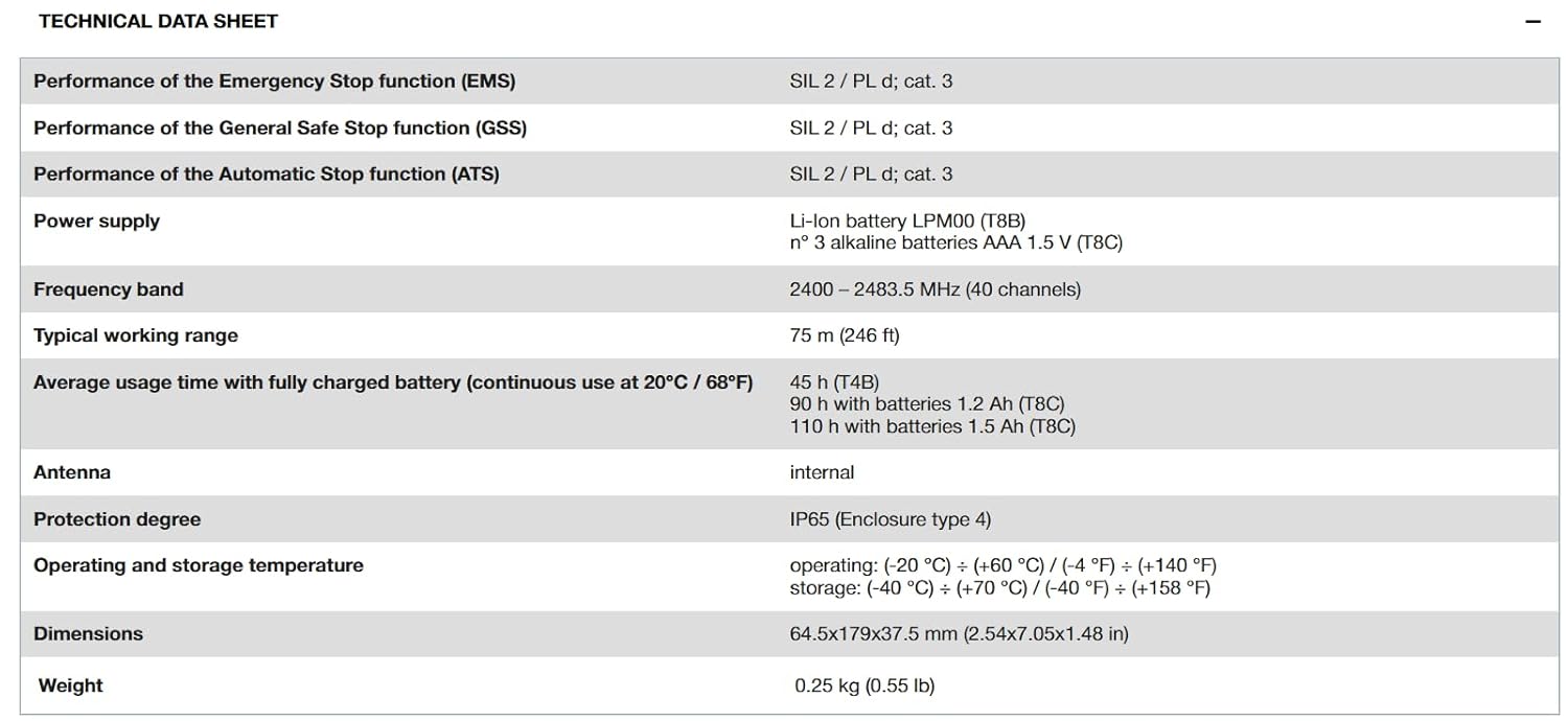
Image: Technical Data Sheet detailing specifications for the AUTEC T8B Transmitting Unit.
| Parameter | Value |
|---|---|
| Performance of Emergency Stop function (EMS) | SIL 2 / PL d; cat. 3 |
| Performance of General Safe Stop function (GSS) | SIL 2 / PL d; cat. 3 |
| Performance of Automatic Stop function (ATS) | SIL 2 / PL d; cat. 3 |
| Power supply | Li-Ion battery LPM00 (T8B) or 3 alkaline batteries AAA 1.5 V (T8C) |
| Frequency band | 2400 – 2483.5 MHz (40 channels) |
| Typical working range | 75 m (246 ft) |
| Average usage time with fully charged battery (continuous use at 20°C / 68°F) | 45 h (T4B), 90 h with batteries 1.2 Ah (T8C), 110 h with batteries 1.5 Ah (T8C) |
| Antenna | internal |
| Protection degree | IP65 (Enclosure type 4) |
| Operating and storage temperature | operating: (-20 °C) ÷ (+60 °C) / (-4 °F) ÷ (+140 °F) storage: (-40 °C) ÷ (+70 °C) / (-40 °F) ÷ (+158 °F) |
| Dimensions | 64.5x179x37.5 mm (2.54x7.05x1.48 in) |
| Weight | 0.25 kg (0.55 lb) |
8.2. ACRH11 Receiving Unit Specifications

Image: Technical Data Sheet detailing specifications for the AUTEC ACRH11 Receiving Unit.
| Parameter | Value |
|---|---|
| Performance of the General Safe Stop function (GSS) | SIL 2 / PL d; cat. 3 |
| Power supply | 24 - 240 VAC (50-60 Hz) |
| Antenna | internal, external optional |
| Max number of Optional Boards | 1 |
| Max number of outputs | 11 |
| Commands rated current | 5 A (250 VAC) |
| Rated current of STOP / Safety outputs | 5 A (250 VAC) |
| Protection degree | IP65 (Enclosure type 4) |
| Operating and storage temperature | operating: (-20 °C) ÷ (+60 °C) / (-4 °F) ÷ (+140 °F) storage: (-40 °C) ÷ (+70 °C) / (-40 °F) ÷ (+158 °F) |
| Connecting interfaces | cable gland M20 and M25, plug 16 and 24 pin |
| Dimensions | 150x134.5x60 mm (5.9x5.29x2.36 in) |
| Weight | 1 kg (2.2 lb) |
9. Warranty and Support
For warranty information, technical support, or service inquiries, please contact your authorized AUTEC dealer or the point of purchase. Keep your purchase receipt and product model number (KT08B001H0) readily available for faster service.
Additional technical documentation may be available using the TU ID: T088701 (for ACRH11) and S/N: LT00077 (for T8B) as reference, though specific links may vary by region or product revision.
Ask a question about this manual
Ask about setup, troubleshooting, compatibility, parts, safety, or missing instructions. Manuals+ will review the question and use this page’s manual context to help answer it.